I’ve restored this cute little Japanese half-frame 35mm camera with a metering conversion from selenium to CdS, and the addition of adjustable focus. Here’s the story.
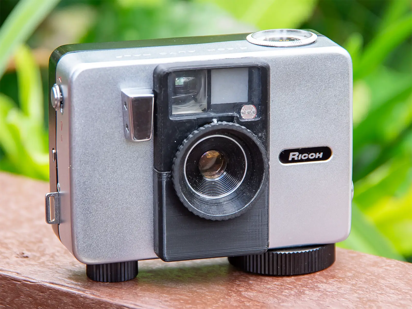
My collection includes different cameras for different purposes or moods. Sometimes it’s great to slow the process down, and agonise over the precise technical details of every shot. Other times it’s more appropriate to just go snap, snap, snap and capture the moment. This tiny Ricoh is great for the latter. It was introduced in 1960, and featured clockwork motor wind that’s good for a dozen or more shots in one go. Being half-frame, it allowed you to snap away for up to 72 portrait-format exposures.
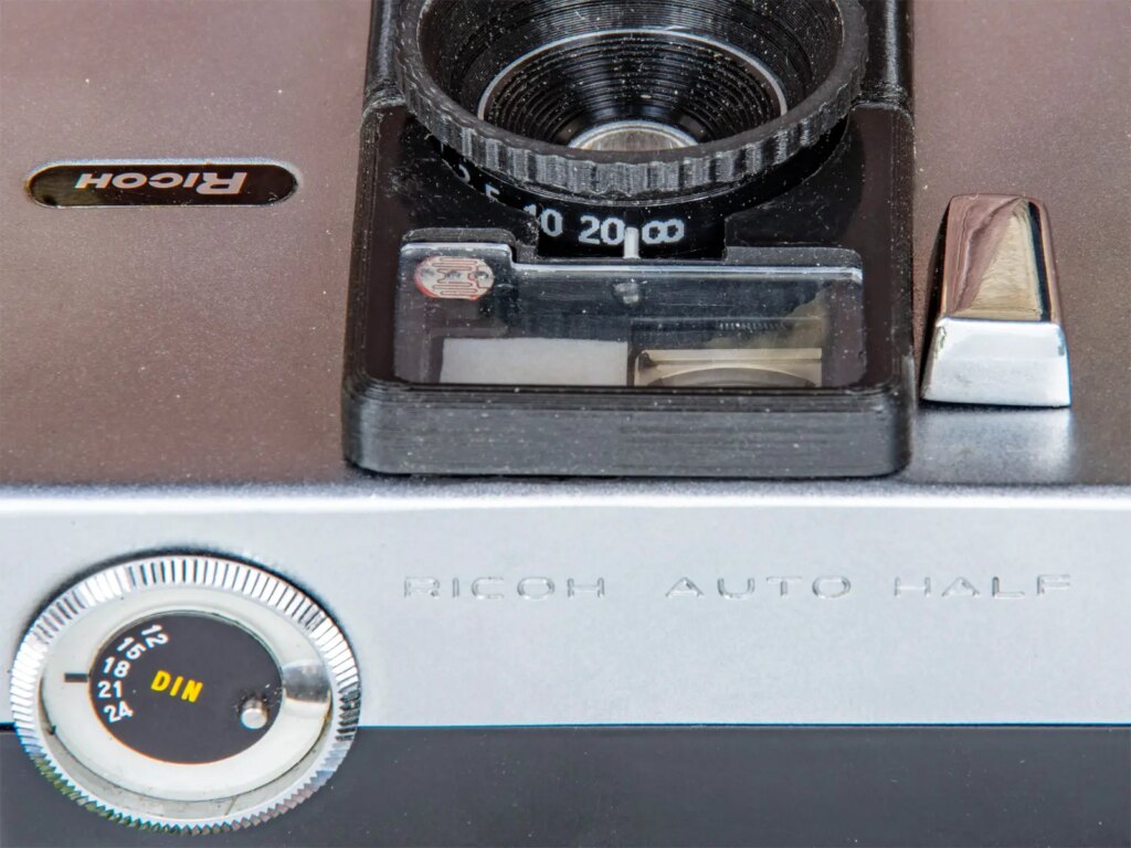
On most versions, the focus of the 25mm f2.8 lens was fixed. The shutter release was initially on the front of the camera, and fires the shutter at about 1/125s when there wasn’t a flashgun connected. Automatic exposure metering used a selenium photocell behind the familiar ‘bubble window’ around the lens, driving a hidden exposure meter and trap-needle mechanism that controlled the opening of the 2-bladed aperture.
Later versions added all sorts of bells and whistles. The shutter release was moved to the top plate, a self-timer was added, and there were multiple fancy coloured finishes from Ricoh and several other licensed brands. A few got fiddly-to-use zone focus, adjusted by turning the front of the miniscule lens rim with downwards pressure from your fingertips. The top-of-the range SL model got a much bigger f1.7 lens with proper zone focus, and battery-operated metering with a CdS sensor, but if you can find a working one it’ll be eye-wateringly expensive.
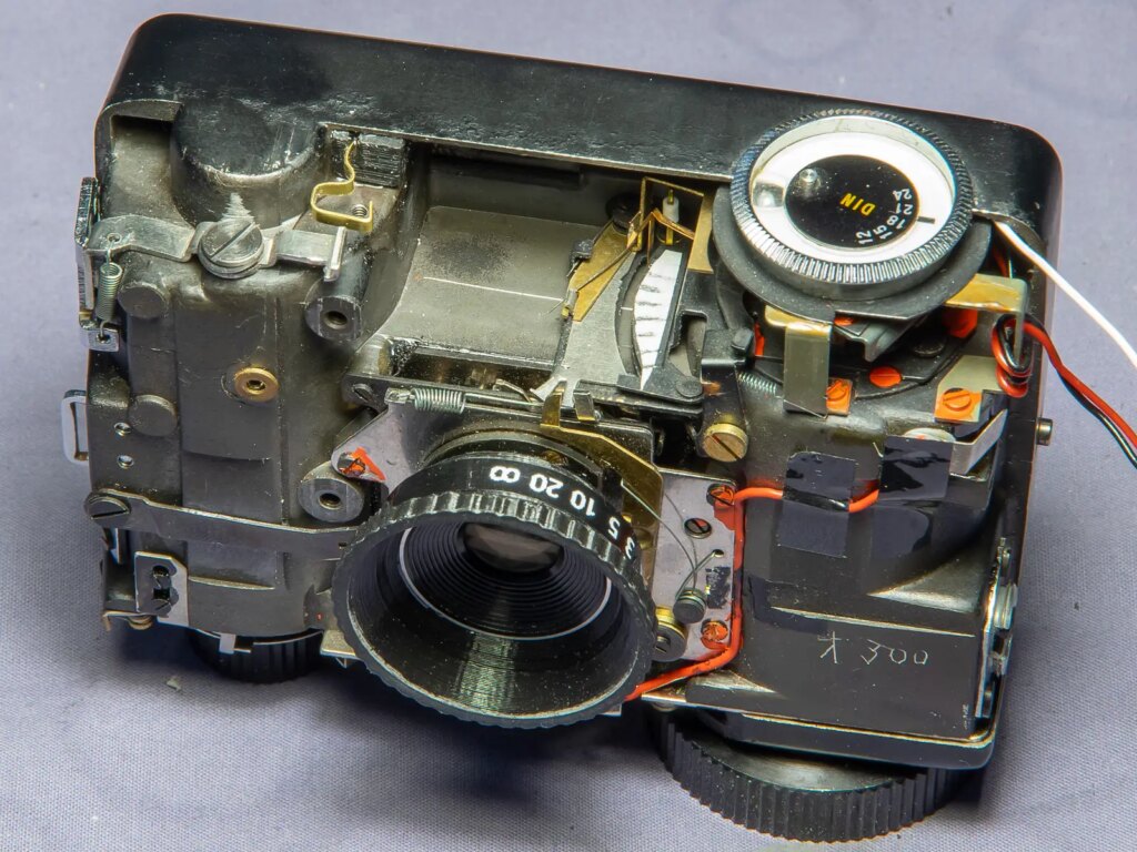
I got my camera cheaply on eBay earlier this year, in nice cosmetic condition and undeclared functionality. It’s the first version, 1960-63. Unsurprisingly, the metering didn’t work. Disassembly and investigation showed that the selenium plate produced only a tiny flicker on the metering needle when exposed to bright light. All of my efforts to improve it failed.
I didn’t want to give up though, so I looked for alternatives. Some people have had success replacing a selenium plate with a solar panel out of a calculator, and re-calibrating the circuit. Not really an option here, because all the panels I could find were much too wide to fit in the narrow housing under the lens.
The next option was to make a battery-powered CdS system to drive the Ricoh’s meter. I had some CdS photoresistors from defunct SLRs in my spares box, and the very simple 1.5 volt circuit diagram used by the old screw-mount Praktica SLRs is available online. Before long I had rigged up a test circuit, using potentiometers mounted in an old takeaway tub, and a CdS sensor placed in front of my calibrated LV light source. In the camera I removed the viewfinder for access and placed a piece of masking tape next to the meter needle path. That enabled me to mark the seven positions that produced apertures from f2.8 to f22 when the trap-needle was operated.
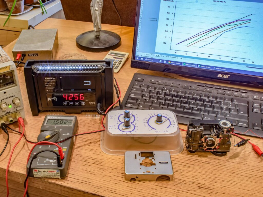
Now I could experiment to determine what changing the resistor values would actually do. It was an iterative process of trying a set of resistance values and noting how the aperture value in the camera changed as the sensor was exposed to varying light levels. Plotting the results in Excel enabled me to see how the resistances in the circuit changed the gradient of the graph, and its vertical offset. After a bit of fiddling, I had a set of resistor values that should work.
Getting it to fit was the next challenge, because this is a palm-sized camera. I designed and 3D-printed a new front housing that is slightly wider than the original, as far as possible while still being symmetrical around the lens and not interfering with the shutter release button. The CdS sensor sits above the lens, behind an enlarged viewfinder window made from an old CD case. The circuit and battery are in a compartment below the lens, behind a sliding cover.
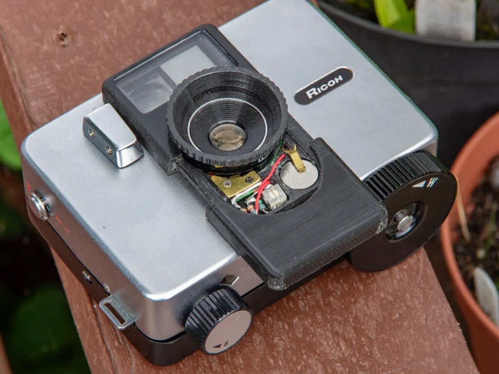
The other practical addition it needed was an on/off switch, to prevent the battery draining when the camera is not in use. There really wasn’t any room for it below the lens. In the end I built one into the camera, so it operates with the shutter lock mechanism. When button on the outside of the camera is slid forward to unlock, the other end of the see-saw locking lever moves backwards to disengage from the shutter release. That end now touches against a springy brass electrical contact I made, and completes the meter circuit. Sorted.
Note the pencil marks against the meter, from f2.8 to f22.
Adding front-element adjustable focus wasn’t too difficult, because the existing housing for the front element screws in and out. It’s set to a distance of about ten feet at the factory, and locked with three grub screws. I removed the grub screws, and glued the housing into a 3D-printed lens hood, which has a decent grip and a focusing scale. A removable brass tab inside the circuit compartment is used to set the infinity stop, and also prevents the lens being unscrewed more than one turn. Due to the lack of space, I had to add a white-painted metal pin to a recess in the front housing to indicate the focus.
The only tricky bit is that there is no ‘B’ setting, which would make focus calibration easier. Instead I worked out where I needed to shove a little sliver of plastic into the shutter release mechanism, to jam it mid-cycle with the shutter open. Then calibrating the focus was simple enough, using an old SLR split-prism focusing screen held against the film rails.
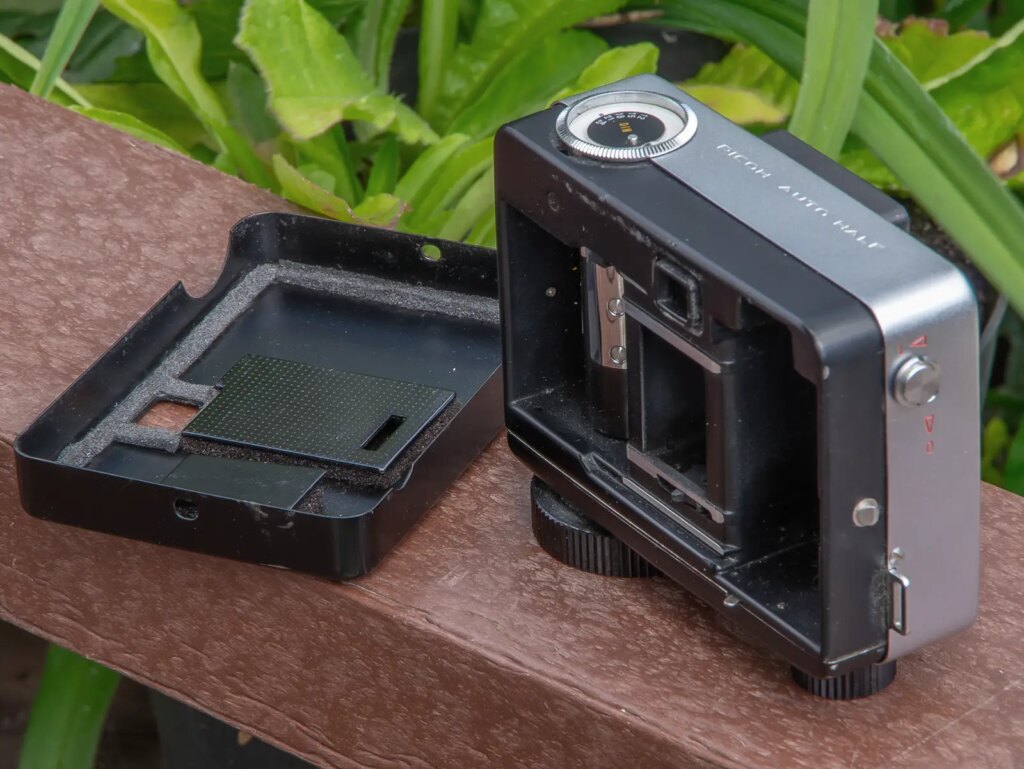
Assembling and testing the camera seemed to indicate that it worked, as the aperture opening changed according to the light level. That justified fitting some new light seals on the rear film door, which is removed completely when loading film.
I loaded a roll of Ilford Delta 100 into it and took it on a couple of photo walks — one around Norwich, and one around the North Norfolk coastal village of Burnham Overy. It’s not really suitable for covert use, because the quiet click of the shutter release is followed by a ‘ZZZZZZUUP!’ noise as you release your finger and the clockwork winder does its thing. Winding the spring uses a silent ratchet though. I got 79 exposures out of the film, and could have got 80 if I’d have loaded it in the dark.
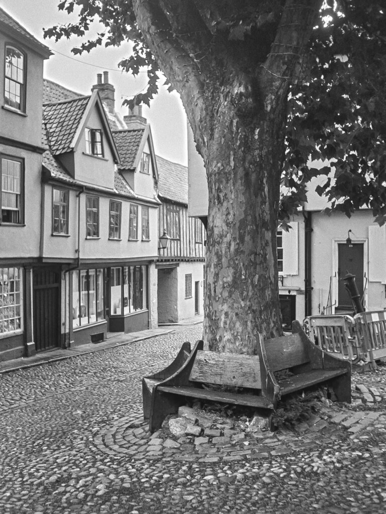
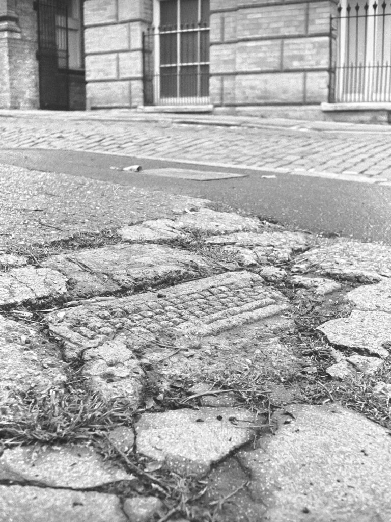
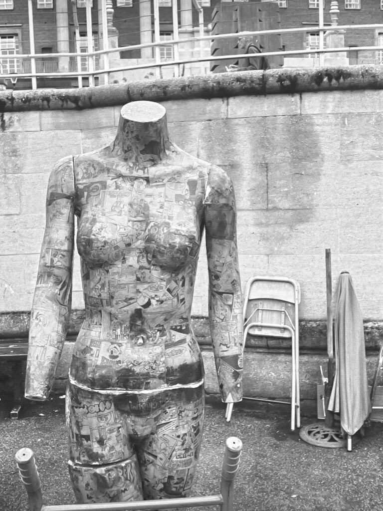

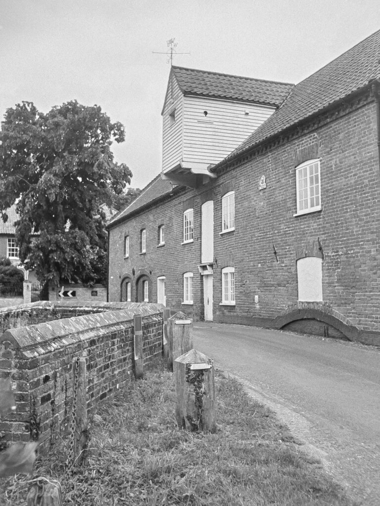
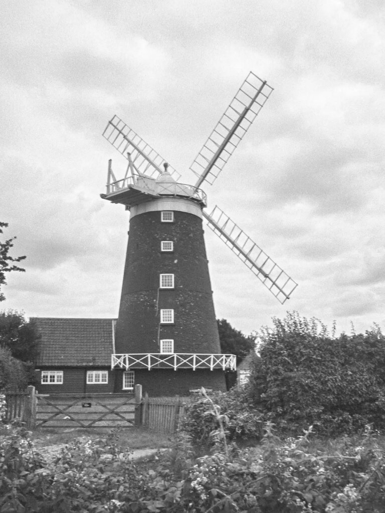
The results were pleasing. Exposures were pretty close to the mark, although it’s still sensible to use a negative film with decent latitude. Being able to focus the camera allowed for a lot more picture opportunities than would have been the case with fixed focus. All the detail is there, and it’s a very usable camera to keep in your pocket.
Share this post:


Comments
Gideon Liddiard on Rescue and Modification of a Ricoh Auto Half
Comment posted: 05/09/2023
Comment posted: 05/09/2023
Bob Janes on Rescue and Modification of a Ricoh Auto Half
Comment posted: 05/09/2023
Comment posted: 05/09/2023
Comment posted: 05/09/2023
Comment posted: 05/09/2023
Keith Devereux on Rescue and Modification of a Ricoh Auto Half
Comment posted: 05/09/2023
Comment posted: 05/09/2023
Timothy C on Rescue and Modification of a Ricoh Auto Half
Comment posted: 05/09/2023
I also tried fixing a later Auto Half to use in the rare underwater housing - and that refused to play ball either - maybe I should send it to you for a makeover and restoration?!
Comment posted: 05/09/2023
Ken on Rescue and Modification of a Ricoh Auto Half
Comment posted: 05/09/2023
Comment posted: 05/09/2023
Zheng Li on Rescue and Modification of a Ricoh Auto Half
Comment posted: 05/09/2023
Stuart Jenkins on Rescue and Modification of a Ricoh Auto Half
Comment posted: 05/09/2023
Uli Buechsenschuetz on Rescue and Modification of a Ricoh Auto Half
Comment posted: 05/09/2023
Comment posted: 05/09/2023
Anthony Bailey on Rescue and Modification of a Ricoh Auto Half
Comment posted: 05/09/2023
Comment posted: 05/09/2023
Simon Cygielski on Rescue and Modification of a Ricoh Auto Half
Comment posted: 06/09/2023
Comment posted: 06/09/2023
JM on Rescue and Modification of a Ricoh Auto Half
Comment posted: 07/09/2023
Comment posted: 07/09/2023
Comment posted: 07/09/2023
Comment posted: 07/09/2023