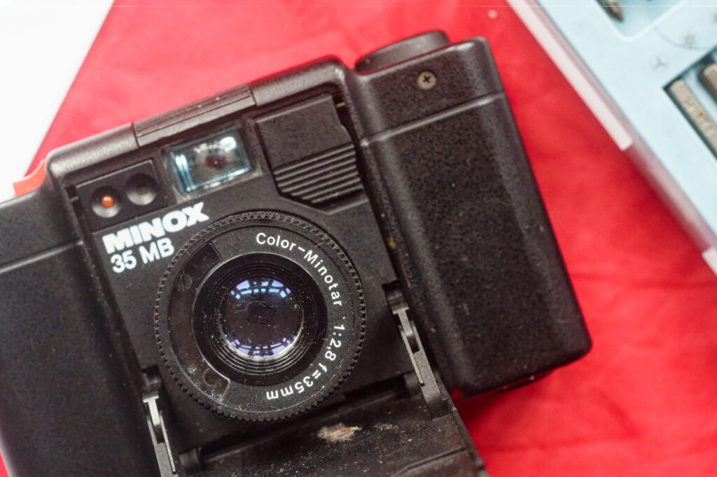
I’m a big fan of the Color-Minotar lens that graces the tiny body of the Minox 35 cameras. About the only thing that annoys me about the lens itself is the misspelling of colour. I’m going to refer to the lens as a Minotar from here on.
I’ve written before about the fragility of tiny intricate cameras with lots of moving parts, and I pondered why Minotars from broken Minox 35 cameras don’t get adapted for mirrorless cameras,
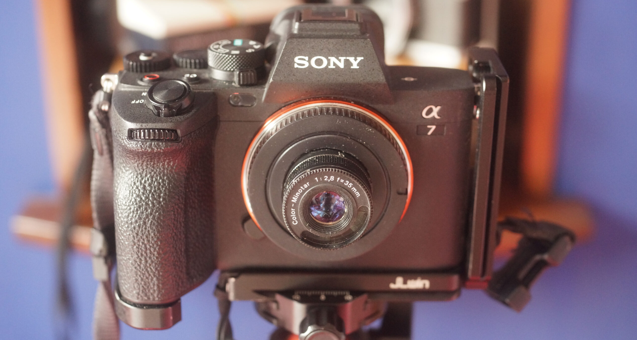
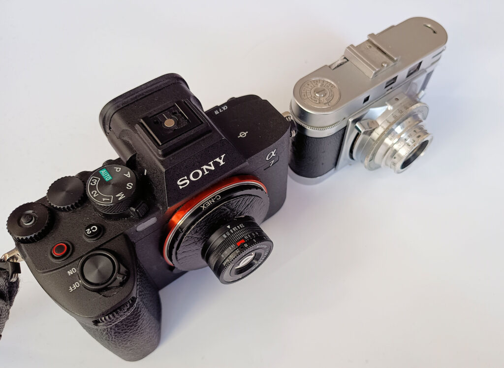
Having more than one malfunctioning Minox 35 and several Sony E-mount digital cameras, I realised that an attempt at adapting was within my grasp. I ended up making two viable conversions, both of which I am documenting here.
Mirrorless Minotar Mk 1 – Bodycap mounting
The donor camera for the Mk1 was a Minox EL. After I’d tried a number of experiments to confirm that the EL was truly dead, I set about an operation with the aim of retrieving the donor lens assembly.
I didn’t know what was required to remove the lens, but I set about a general disassembly. I was a bit more organized when it came to the Mk 2. That disassembly is documented later in this article, and is broadly the same as for the EL. Basically, I found that the way to release the lens was to start undoing screws in the film chamber and keep going. Eventually, the whole lens assembly comes free.

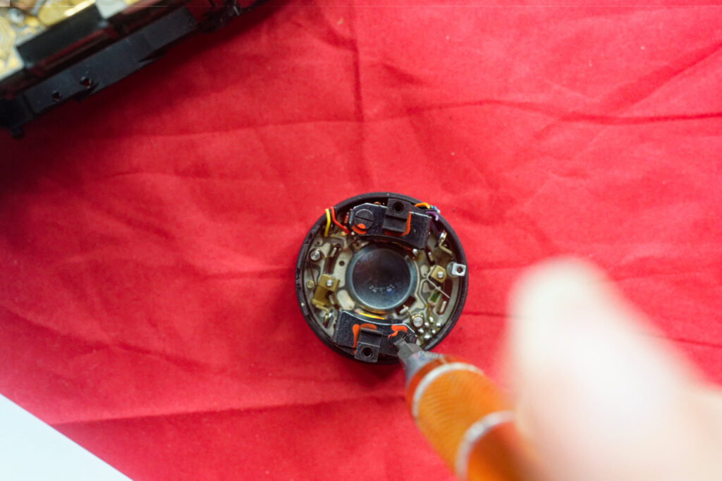
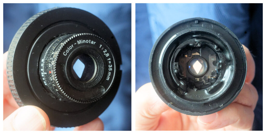
The EL lens assembly sits on three metal legs. The assembly includes an aperture ring controlling a two-bladed diaphragm that forms a kite-to-diamond-shaped aperture. It also contains a couple of solenoids to open and close the shutter blades and wires that connect the CdS cell to the camera’s meter.
I removed the solenoids and cut the wire to the meter. I set the little catches at the back of the lens so that the shutter was left permanently open. I retained the mounting ring that the lens assembly’s legs fit inside and which (on the EL) has the aperture values inscribed on it (it is slightly different with the later cameras). With hindsight there were other useful bits of the camera carcass that I discarded that I could have used. For instance, the mounting plate and baffle (see later).
For the mount, I used a cheap E-mount body cap from an auction site. I’ve done this conversion for E-mount, but it should be possible to do the same for any other mirrorless mount that will take ‘dumb’ adapters by using similar body caps.
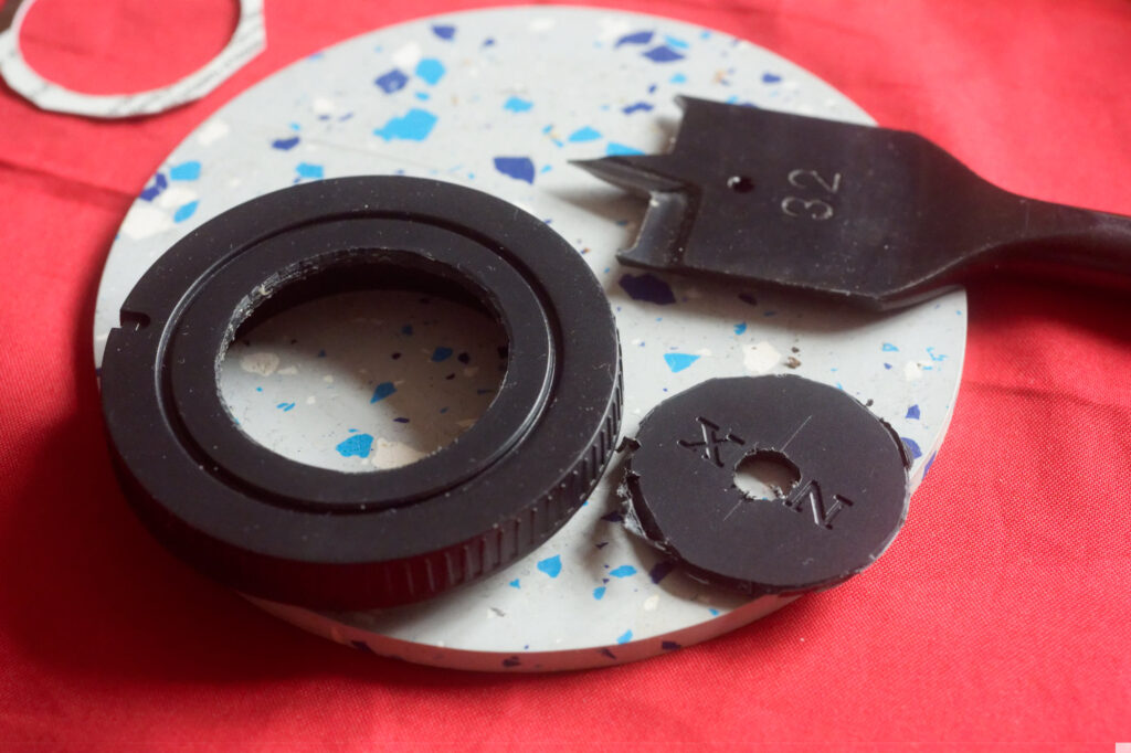
The diameter of the EL lens assembly is about 30-31mm across, with a nice lip at the bottom of the mounting ring that extends about another 2mm for most of its circumference at the base. I got a flat 32mm drill bit for wood and took out a centre hole in the body cap. The particular tool I was using cut deeper at the periphery of the hole, so by drilling one side and then going from the other, I was able to remove the disk of plastic without having to create too much in the way of plastic shavings.
Now came the awkward part – finding the position that the lens needed to the placed it order to get infinity focus and a full range of focus distances.
The little Tessar-type lens focuses by a relatively small movement of the front group of elements. This is great for a compact lens, but makes positioning the lens at the right distance from the sensor all the more critical.
I used a process of trial and error. Initially, I tried simply holding the mounting ring and lens against the inside of the body cap and used a mirrorless camera’s focus peaking to confirm that the lens assembly needed to be set slightly back from the rear of the body cap. To hold everything in place I used a PVA-type glue that would set enough to hold everything in place temporarily, but could then be removed for further adjustments. Use of the PVA introduced some delays waiting for it to dry. An alternative might be to hold things together with elastic bands or something like a jubilee clip, but the PVA method worked reasonably well and just involved a little patience.

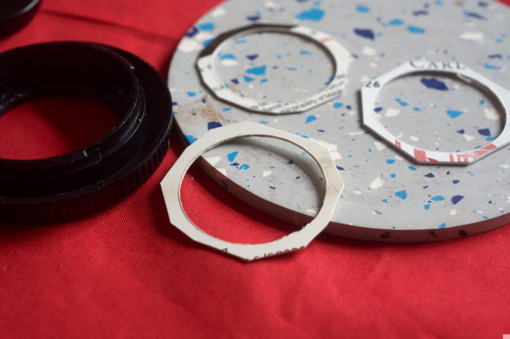
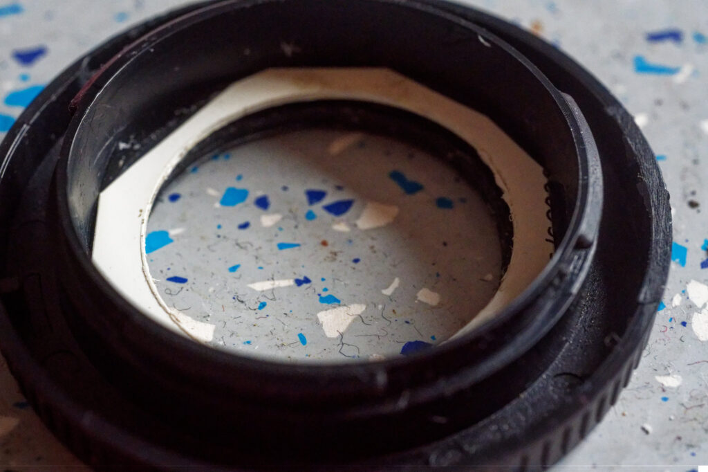
To get the assembly a set distance back from the rear of the body cap, I made myself a series of shims from old store and ID cards, which were each about 1mm thick. I bored a hole in them with the flat 32mm bit and then roughly cut the outsides so they would fit into the body-cap void. This gave me a series of shims to experiment with. In the end, for my combination of lens and body-cap, I only needed a single shim to give a decent focus peaking on a far object and was able to confirm that the distance scale seemed reasonably accurate for closer items. Anyone doing a similar conversion needs to remember that body caps are unlikely to be standard (or even made to particular tolerances), so they will need to do their own calibration.
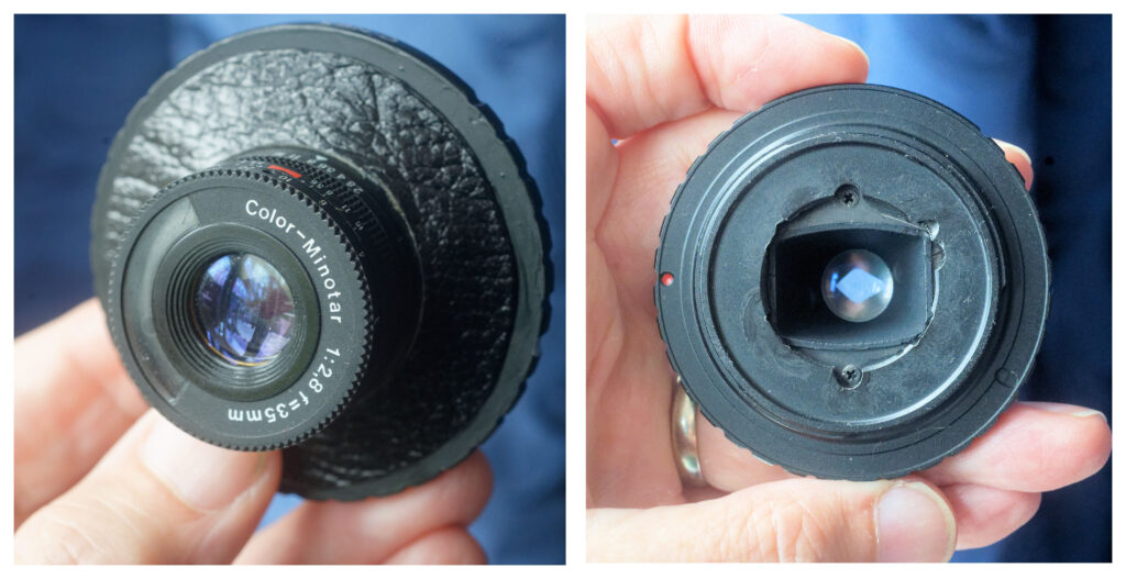
I cemented the lens in place, deliberately putting the focus and aperture scales on the side of the lens mount, with the idea that I might do a further mod to cement a focusing lever over the bit of the front of the lens that the CdS cell used to look through (a mod I’ve not done as yet). I misjudged this slightly, leaving the index marks a little below the 9 o’clock position I’d intended.
Mirrorless Minotar Mk 2 – C-mount
Having produced a working Mirrorless Minotar, I considered what could be done better.
While body-caps are cheap and reasonably easy to work on, they are not manufactured to be consistent, so there is no guarantee that the shimming that gives the correct infinity focus on one build would be the same as on another. Body caps also don’t lock in place.
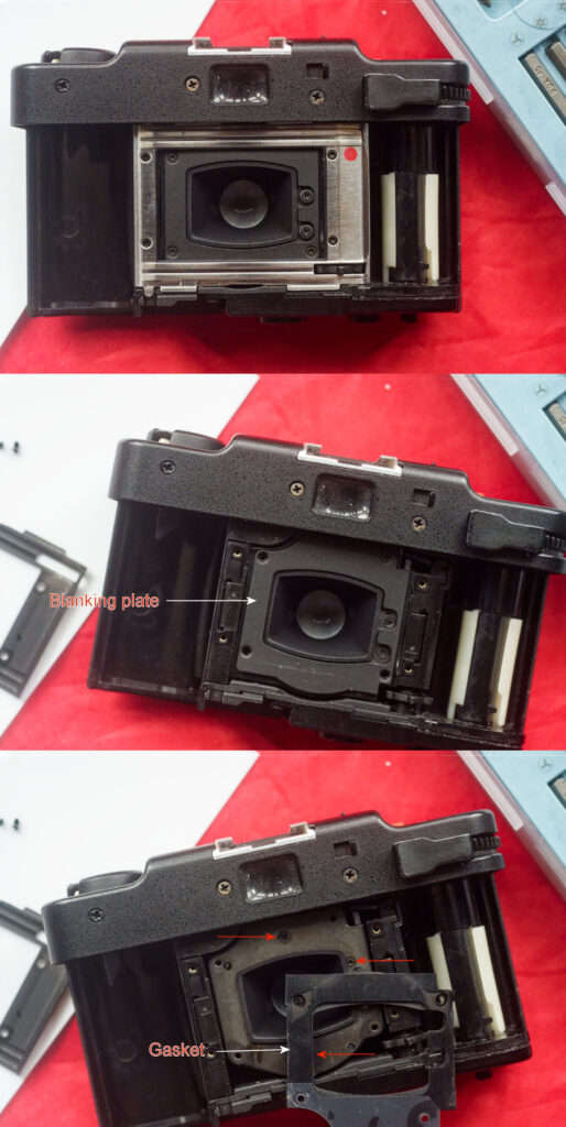
I realized (quite late on) that I could measure the distance from the film plane to the back of the blanking plate on a working Minox 35. Using a vernier caliper with a depth gauge on my remaining (working) 35 EL, I found that the blanking plate for the lens with the door open is 17mm from the film plane. The blanking plate and gasket (which sit just behind the mounting plate) measure just over 1mm, so we should be positioning the back of the mounting plate about 18mm from the film/sensor plane. which is quite close to where C-mount puts us.
C-mount adapters are made for a variety of mirrorless cameras. The flange distance for C mount is standard and at 17.526mm is reasonably close to the flange distance used for mirrorless mounts (16mm for Z, 17.7mm for X, 18mm for E and EF-M, 19.5mm for M43 and 20mm for RF and L). Rather than attaching and shimming from the back of a body-cap, the C mount would open up the possibility of keeping more of the lens assembly together and judging any shimming required from a surface of a known distance that would be applicable to all mirrorless interchangeable mounts.
The donor camera for the Mk 2 was a Minox 35 MB. After confirming that it really was no longer functional as an analogue camera, I set about stripping out the lens assembly.
The thing that hit me when I started to strip down the MB, is just how much had changed since the EL. The EL is a quite basic camera, while the MB shows signs of added sophistication (and streamlined manufacture).
Differences between the EL and MB lens units.
As you would expect, there were various changes over the years between the introduction of the EL and the restyled MB cameras.
The EL mounts its lens assembly on three metal legs, while the MB uses two main plastic legs with a third metal leg to one side.
The design of the shutter also changed; the EL uses a two-blade shutter, while the MB lens has three. The focus ring on my MB is also much freer to turn than the one on the EL, although this could be down to sample variation.
Crucially for anyone thinking of going down the Mk1 route, the MB lens assembly is slightly wider at 32mm, while the ‘step’ in the mounting ring that would rest against the shim on the inside of the body cap is shallower. I’d recommend still cutting a 32mm hole, but maybe have some glass paper handy to open up the hole a little if required.
Stripping the lens assembly out of the Minox 35MB
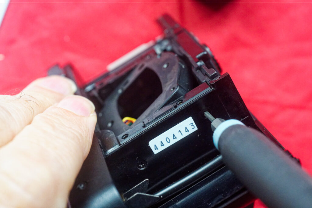
To remove the plate that the lens mounted to, you need to undo the screws at the side of the cassette and take-up chambers. The ones on the take-up side can be awkward to reach, but you might get away with just removing the left side.
Red paint and narrow slots are a good sign that the manufacturer really didn’t think you should be undoing these, but we have no need of a shutter. At the 3 o’clock, 4 o’clock and 10 o’clock positions you can see little silver tabs – fiddle with these until the shutter is left open.
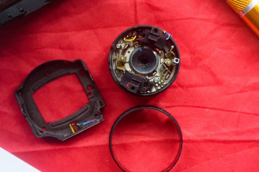
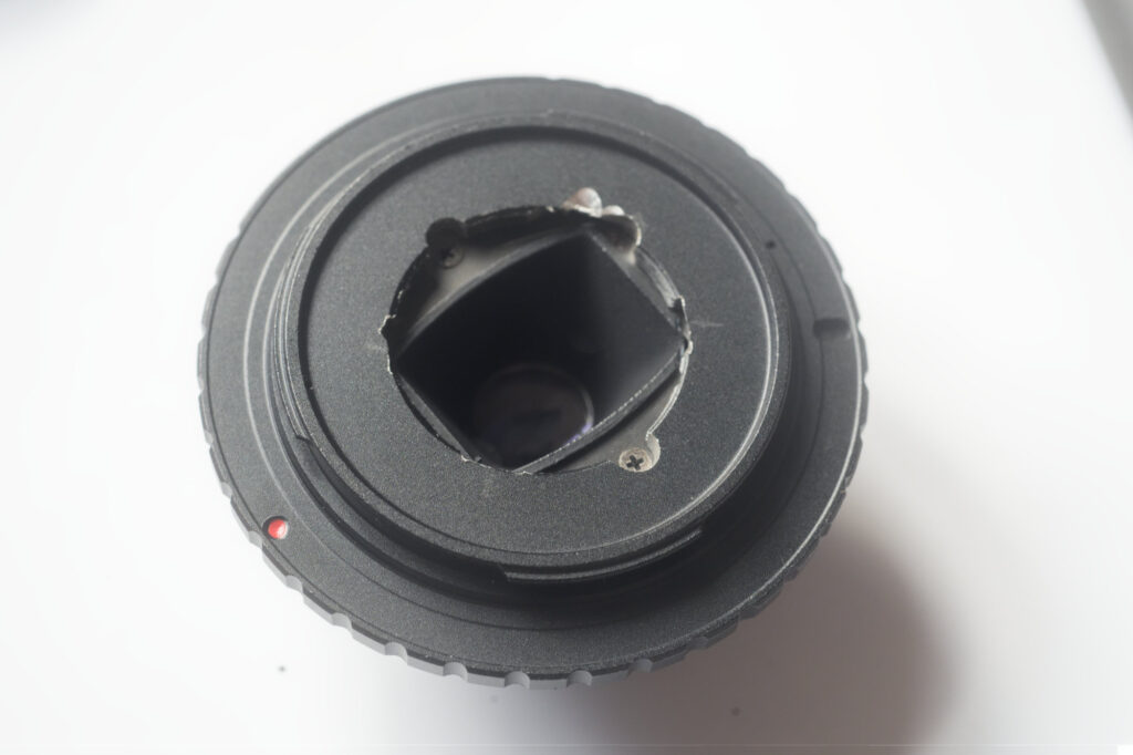
With reference to the picture above, I’m going to call the bit on the left the mounting plate, while the bit at the top is what I’m calling the lens assembly (including shutter, aperture blades and optics). At the bottom we have the mounting ring, which fits between the mounting plate and the lens assembly, located into the mounting plate by a little ‘pips’ on its rear edge. The lens assembly fits into the ring and can be secured to the mounting plate with the original three screws.
Above, you can see the lens assembly sitting inside the mounting ring. Be sure to retain the little baffle that fits into the mounting plate, as this does a nice job of stopping stray light reflecting off bits of metal at the back of the lens assembly.
A slight pause here, while things go wrong
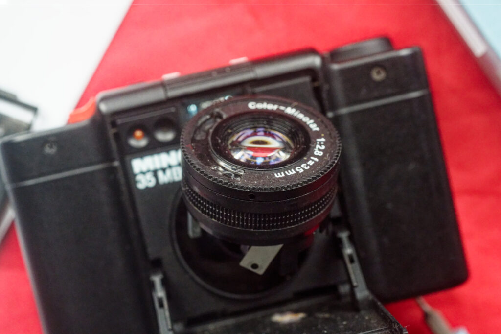
My intention was very much to leave the lens assembly whole and not delve in there; however, after removing the remains of the wiring from the MB assembly, I noticed that one of the shutter blades had become dislodged, with part of the loose shutter blade partially obstructing the light path.
In desperation, I ended up going into the lens from the front.
The focus ring comes off with the slackening of three tiny grub-screws on the edge of the focus ring (which requires a really small flat-bladed screwdriver). The focusing element of the Tessar-alike then has to be unscrewed to allow the next plate to be removed. I worked my way on down through the lens towards the errant shutter blades..
Things got worse before they got better. One plate was holding the aperture blades in place. I was hoping to leave stuff intact as much as possible, but suddenly bits dropped out and I was left with two oddly-shaped aperture blades on my workspace without a view on how they fitted back. I realised that I might be ending up with a woefully out-of-calibration lens with a fixed aperture, but by this time, the fate of my little project was rather reliant on shifting the stray shutter blade. Next level down, I reached the shutter. As the shutter blades will have no function for the lens in its mirrorless-mount form, I removed them entirely and replaced the level that holds the aperture blades.
I was lucky to work out how the two aperture blades sat on two tiny raised pins, with the pin on one blade going through a slot on the other. The plate that holds these in place has a slot in it to allow the pin to poke through, the plate also has a little captive spring to hold the aperture open by default. The plastic aperture ring that sits on this has slots that engage with the pin and hold it in against the spring for the smaller apertures. The ring with the DoF scale on it sits on top of this. Once the lower levels are in place, the focusing element needs to be screwed back in place. It is a horribly fine thread. It should turn reasonably easily; if you get any resistance, you might be cross-threading it. I ended up calibrating the lens on a far object with focus peaking before re-attaching the focusing ring and tightening its little grub-screws in turn.
I think I got away with it. On the whole, I’d say to avoid opening up the optical part of the lens assembly itself unless it is absolutely necessary, but it is possible to get it all back together and working (or at least, working for use as a mirrorless lens). If you do venture into the lens from the front keep a careful note of what screws go where. There is a frightening variety of sizes (both cross and slot-head) and I was left wishing that I’d documented things better in my panic to save the lens.
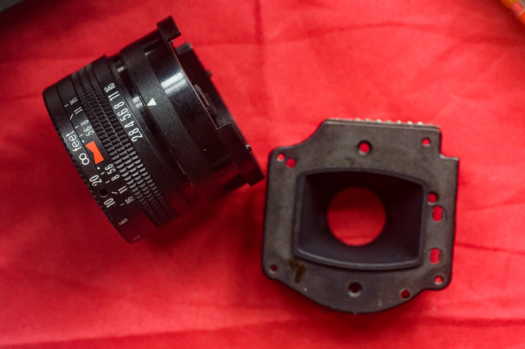
C-Mount adapter
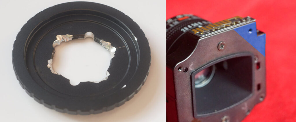
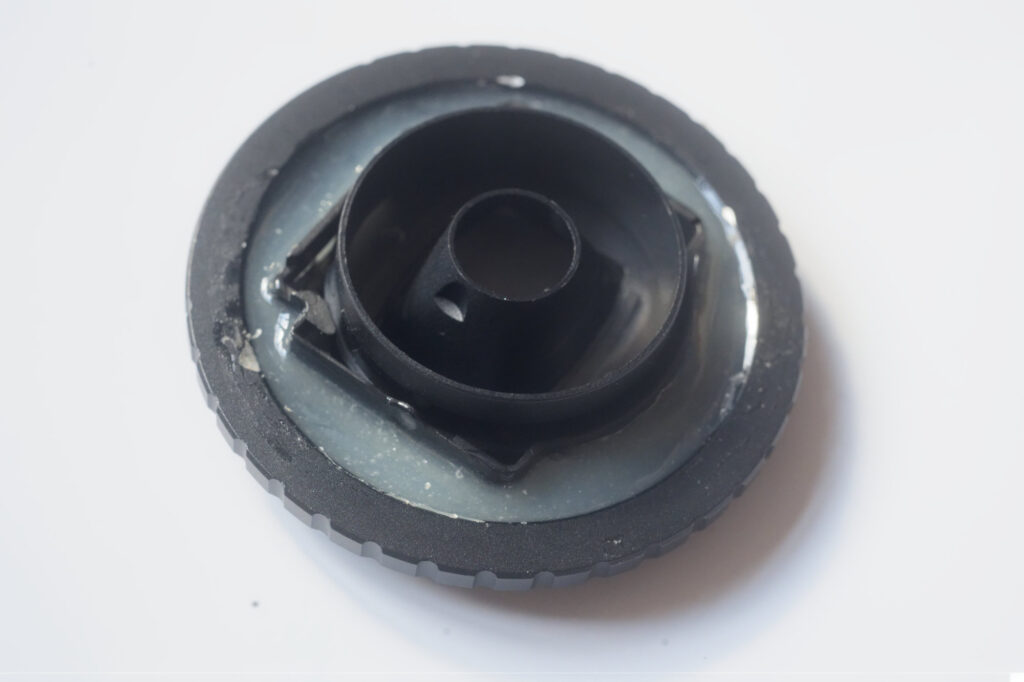
Note that the C-mount adapter has a little ‘step’ in the well. Luckily, three of the corners of the mounting plate fit inside this step, with only the top right corner, which has the circuit board on it, getting in the way. To get around this, I simply removed the circuit board and filed down the bit of the back of the mounting plate (shaded blue in the picture above) by a few millimeters, so it would fit over the step.
The C-mount adapter has a one-inch threaded hole. I used a rat-tail file to allow access to the screw heads that hold the lens assembly onto the mounting plate (so I could replace or work on the lens assembly if required). I also filed away some of the mount so that it would not obstruct the corners of the frame and so that I could get the baffle in and out once the mounting plate was glued in place.
This is the point to make sure that the lens is focusing as expected. Check that you can get infinity focus and that when you focus on something closer, the distance scale matches how far you are away from what you are focusing on. Only apply epoxy when you are sure everything is as it should be…
Reviewing the results
On the whole, the Mk 1 is perfectly serviceable, and the plastic of the body cap is slightly easier to shape, but the Mk 2 feels more substantial. If I were having another go at a Mk 1, I’d add in the backing plate and baffle. The backing plate would have to be reversed (or to have the side ‘walls’ removed), but could still be attached to the lens assembly by at least two of the screws to the legs.
The Mk 2 is left a little ‘unusual looking’ from the front, but things could be improved there by using plastic padding to fill in some of the voids before adding some black paint. I initially I covered the front in a bit of calf’s leather from an old wallet.
If you are looking at the Mk 1 route and working with Z mount (16mm flange distance), you might find that mounting the lens inside the cap puts the lens too close to the sensor, so you might have to look at attaching it to the front of the body cap (depending on how deep Z-mount body caps are). If you are adapting for RF or L, you might have to use a few more shims than I did for my Mk 1. For Fuji X you might be close enough with a thin shim. A lot depends on the particular body caps used (which is part of the attraction of the Mk 2 for me).
If adapting for other mounts that will take a C-mount, you should get very near to the correct distance for proper infinity focus by simply attaching the Minox lens assembly and mounting plate to the front of the mount as I have described above (but please check before you do anything irrevocable).
Cosmetics
After I’d finished to conversions, I looked around for ways of improving the finish on both versions, experimenting with disks cut from wood veneer, Makrolon and leather, as well as large washers and bits salvaged from old cameras. There is lots of scope for individuality here, and I give you some possible variants..
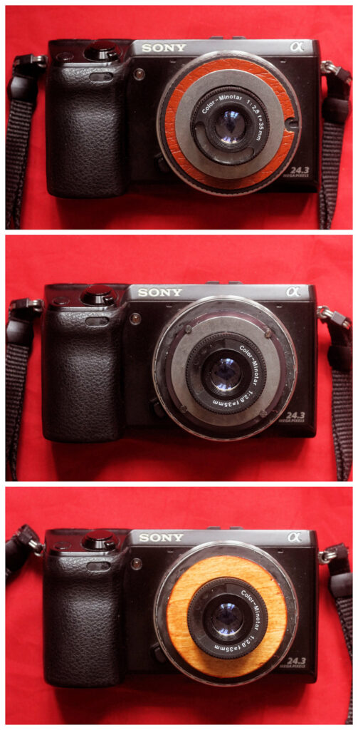

The leather for the Mk 1 is simply cut from an old wallet, topped with a 32x45mm shim washer. The ring for the Mk 2 was quite a find, as it comes from a broken Balda microscope camera, so it has a family connection. You need to be careful when using the earlier EL lens if you want the original f-stop numbers to remain visible.
Pictures
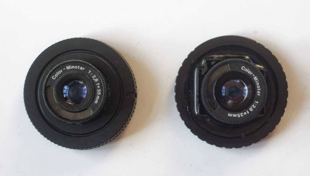
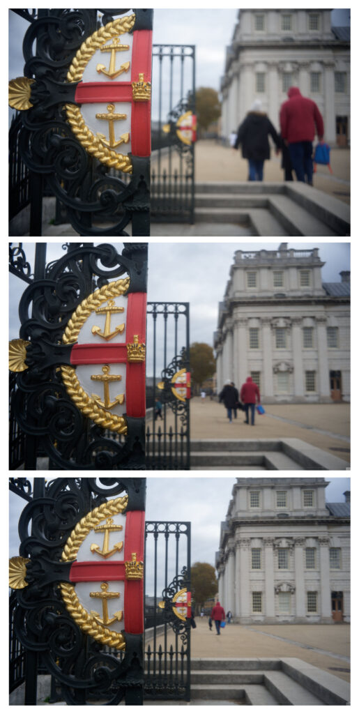
Just to prove that the whole thing works (to myself as much as to anyone else), I took a trip into Greenwich. I did take various comparison shots with both lenses, but to be honest there was absolutely no difference between the results from either version – suggesting that, while the shutter and mountings may have altered over the production run from EL to MB, the optical formula seems to be exactly the same.


The bottom line
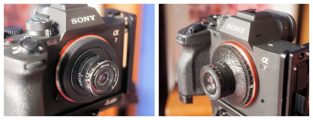
Such a tiny lens sitting like a pimple on a relatively large mirrorless camera body does not look impressive, but I hope the photographic results justify this experiment. I’m not sure how much I’ll use either of these lenses, but the whole process has scratched an itch and through it I’ve managed to give some purpose to two lenses that would otherwise have been totally redundant.
At the very least, I’ve reduced the number of broken cameras in the house by 2!
On the whole, I’d say that the best place for a Color-Minotar lens is a working analogue Minox 35, but if you have one on a dead Minox you may be able to give it new life.
If anyone else has done a conversion, or if someone does one after reading this article, I’d be fascinated to hear about your experiences in the comments.
Share this post:

Comments
Jonathan Leavitt on Minotars for mirrorless – Converting Minox 35 lenses for use on digital bodies
Comment posted: 23/11/2025
https://www.dropbox.com/scl/fo/nzdok02uj1jk86ebcmllu/AOeI88L2y-l24hv4SbsDOZY?rlkey=uz948sslmc7gjzokax0uokm1m&dl=0
Comment posted: 23/11/2025
Comment posted: 23/11/2025
LAOWUTONG on Minotars for mirrorless – Converting Minox 35 lenses for use on digital bodies
Comment posted: 23/11/2025
Comment posted: 23/11/2025