1.Introduction
The shutter setting has been an essential part in photography. The modern digital cameras relay on electronic shutter which precisely controls the on and off the pixels on the CMOS sensor. The later-model film cameras like the Canon EOS 3 or Nikon F100 incorporate more accurate electronically controlled shutters. The shutter accuracy has never been an issue for those cameras in ordinary photography. However, most of the old mechanical cameras suffer from wear, spring fatigue, degraded lubrication and misalignment which results in considerable error in shutter speed, making the correct exposure impossible and causing economical damage by ruining a whole roll of precious film. Therefore, for old school photographers who enjoy purchasing and shooting with used pure mechanical film cameras, the shutter performance evaluation can be of great importance.
The shutters in ordinary commercial cameras can be divided into 2 types: between the lens shutter (leaf shutter) and focal plane shutter. The leaf shutter is generally used in rangefinder camera, twin-lens 120 format camera and large format camera. In this shutter, once the bottom is pushed, the leaf will quickly open up the aperture until it reaches the pre-set F-number. Then, the aperture will stay open for a while using a retarding mechanism. Finally, the leaf will close again and finish the exposure process. The focal plane shutter is generally applied in most of the SLR cameras. This shutter consists of a light-proof curtain with a transparent slit on it, located very close to the focal plane. Once the bottom is pushed, the curtain will slide across the focal plane and the film will be exposed through the slit. This means that in high-speed focal plane shutter the film is exposed strip-by-strip while the film is exposed entirely by leaf shutter. However, when the shutter time is relatively large (for example, large than 1/250 s), the focal plane shutter will also be entirely open for a certain period of time.
The general exposure process of a leaf shutter is shown in Figure 1. Phase A and phase C represent the opening and closing of the aperture. These 2 segments are linear and almost identical. The exposure process described by Figure 1 happens simultaneously among the film area for leaf shutters. The T1 shown in Figure 1 is referred to as the total open time, which is the time for the shutter to finish a single exposure process. The effective exposure time Te which is measured by the amount of light is T1 * (area of the shadow region), which is less than T1. The ratio between Te and T1 (Te/T1) is known as shutter efficiency. For a leaf camera, the efficiency is affected by the shutter speed and aperture setting and is usually ranging from 60% – 90%. For a focal plane shutter, the exposure process for a small area on the film is similar to that of Figure 1, only the A and C segments will be nonlinear. Due to the strip-by-strip exposure, this curve only applies for the small area on the film where the slit is passing through for focal plane shutter. Usually, the efficiency of a focal plane shutter is quite high and the rising edge (A segment) and falling edge (segment C) is quite sharp. Therefore, it’s reasonable to consider that the effective time Te is very close to the total time T1. It’s only when there exists a considerable distance between the shutter surface and focal plane that the Te can be significantly less than T1, such as in some aerial camera. More details and backgrounds of shutter can be found in [1] and [2].
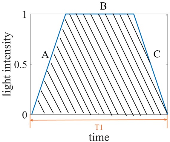
Figure 1 General exposure process of leaf shutter
The testing and metrology methods for camera shutters are not very new technology. Generally speaking, other than the film testing, there are 2 methods for shutter speed testing: direct method and motion-blur method. In the direct method, the behavior of the shutter is directly observed and recorded for analysis. In the motion-blur method, pictures of artifacts are taken with the shutter being measured. The shutter speed can be obtained by analyzing the motion-blur pattern of the final image. An overview of the widely applied shutter testing methods in professional and academic level can be found in [3-4]. There have already been multiple articles about this subject on the Internet. For example, in [5] a device based on motion-blur created by a rotating disk is developed. A device based on photodiode to directly measure the shutter time is demonstrated in [6]. In [7], an audio recording-based method is presented. However, most of the projects require complicated mechanical structures and electronic circuits which makes the implementation quite complicated for someone without a lab or garage and many gears. There are also commercially available products, such as the vfm series on eBay. The earlier versions of vfm devices relay on audio recording and need to connect to computer for data processing. The latest versions, such as vfm31, are much more capable and convenient. However, the vfm31 and similar devices can be expensive, costing at least 85 dollars.
In this article, a setup based on direct method and light sensor for shutter testing is proposed. The setups are quite straightforward with readily available mechanical and electrical components. Multiple setups and alternative components and solutions are discussed. The cost of the devices is also included. Following this introduction, the paper is structured as follows: Section 2 describes the general methodology of the proposed method, Section 3 presents the experimental setup and some results, and Section 4 includes the conclusion and future work.
2.Methodology
2.1 general schematic diagram
The general schematic diagram of the proposed method can be shown in Figure 2. A light source, which can be either an ordinary light or a laser diode, is placed in front of the shutter being tested. A light sensor is set right after the shutter to receive the light when the shutter is open. A data acquisition device samples the signal from light sensor and transmits the data to computer or other data processing device. The shutter time is then calculated as the time difference between the rising edge and falling edge of the collected light sensor signal.
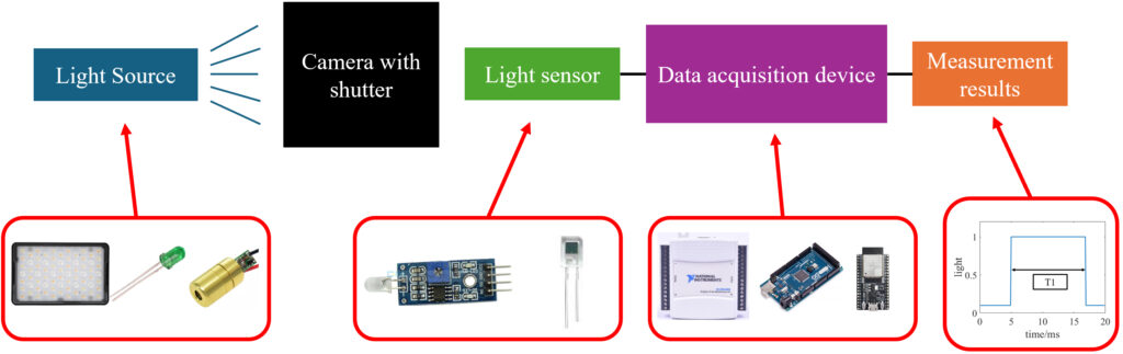
Figure 2 The schematic diagram of the proposed method
It is worth mentioning that this method is more suitable for testing the focal plane shutter with high efficiency, since the single photodiode light sensor cannot accurately characterize the detailed opening and closing process of a lead shutter. This effect is especially pronounced when using a laser diode at the center of a leaf shutter. The measurement result will be significantly larger since the total shutter time T1 rather than effective shutter time Te is measured. However, if carefully placing the laser beam at different radical positions of the leaf shutter and analyzing all the data, it’s still possible to fully characterize the leaf shutter behavior.
2.2 Setup 1
In setup 1, a photodiode sensor which is generally used with Arduino device was applied as the light detector. The photo and circuit structure of this module, which is from an eBay link: https://ebay.us/m/erVWJY, is shown in Figure 3. This device contains a photodiode and an LM393 Dual differential comparator. It’s worth mentioning that there are several very similar modules on the market which use photoresistor as the sensing device. These photoresistor based modules might not be suitable for our task due to their considerably slower response time in the scale of ms or even larger.
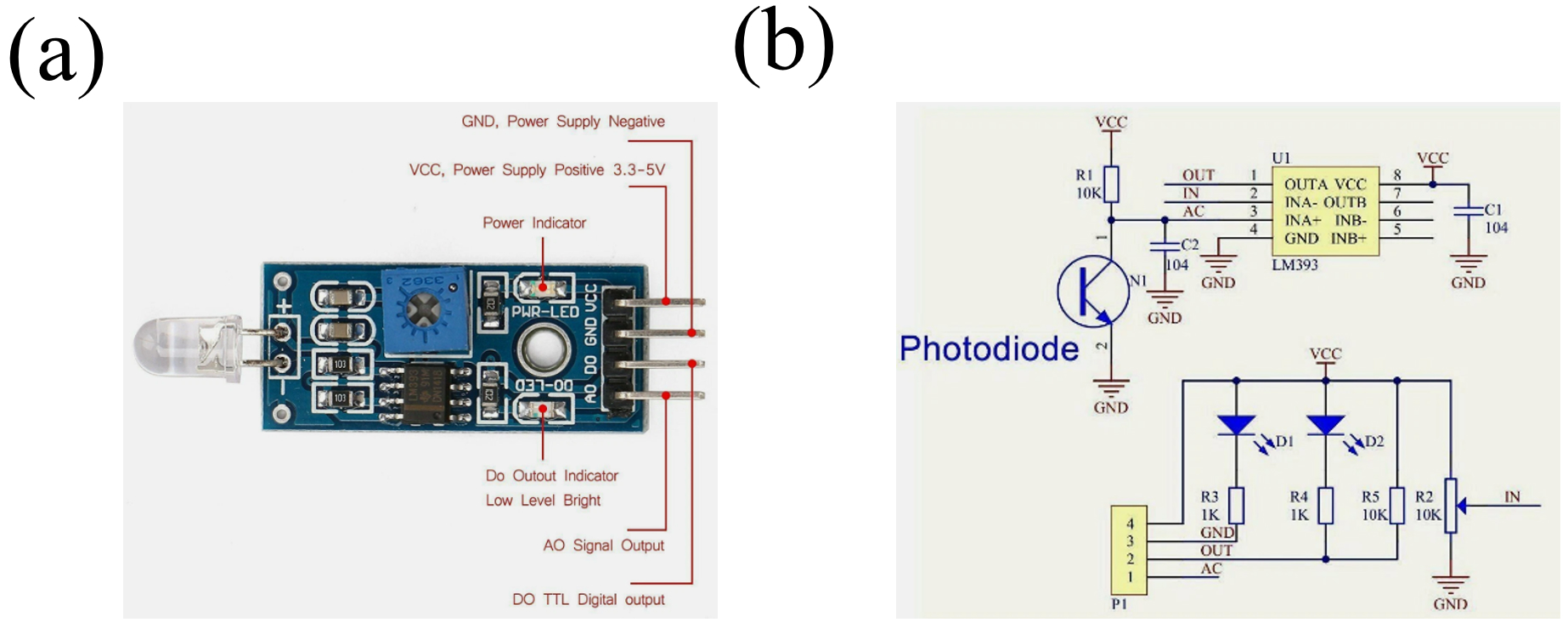
Figure 3 The structure of the light sensing module applied in setup 1: (a) photo, (b) electronic circuit layout
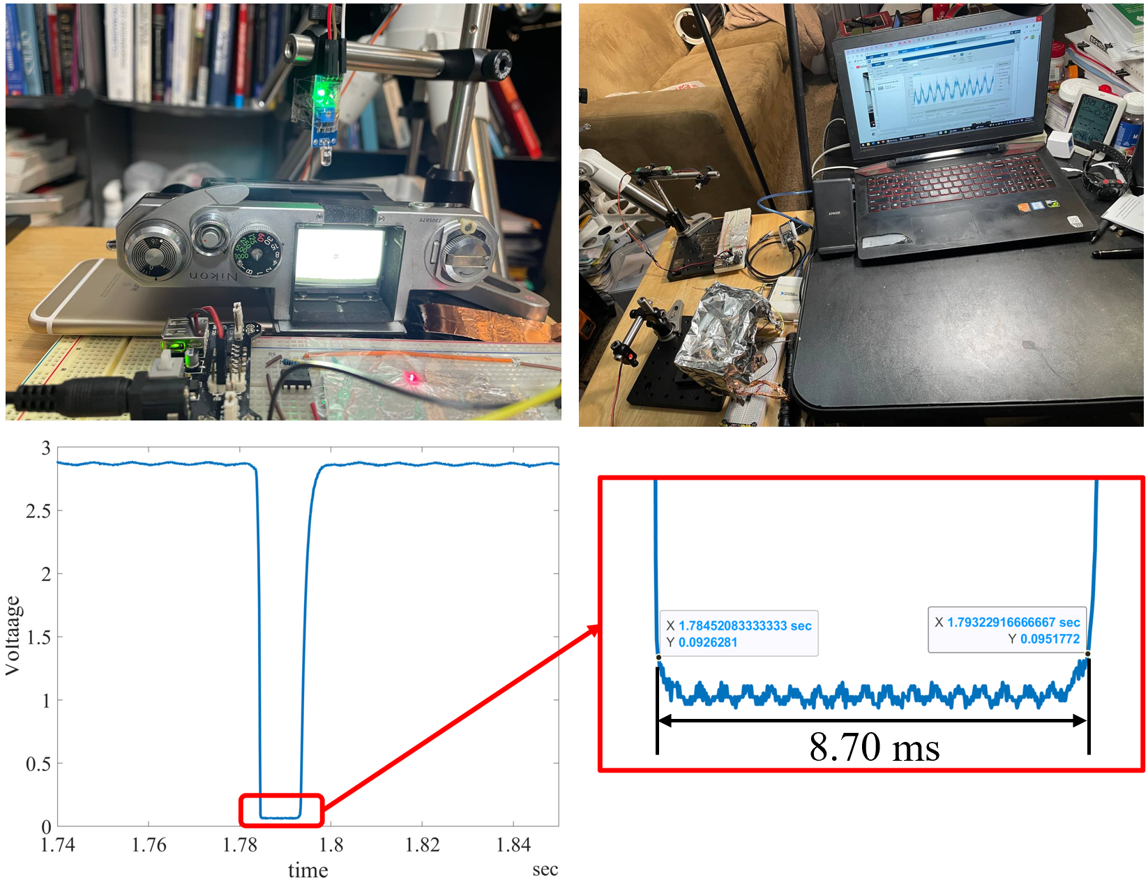
The photo of the setup 1 is shown in Figure 4. An iPhone 6 with its flashlight on is used as the light source. The light sensing module is clamped right above the shutter. A 5V DC power source is connected to a small power module on the breadboard, which powers up the light sensing modules. The circuits on the breadboard is not related to this setup. The analog output as well as the ground is connected to a NI6009 data acquisition device (14-Bit accuracy, 48 kHz sampling rate). Either professional software such as LabVIEW and MATLAB or open source software such as python package nidaqmx can be used to control the device and record data. To reproduce this setup, a magnetic based clamper can also be used, with the light sensor module attached with tape, as shown in Figure 5. This clamper can be firmly attached to a metal table and is very flexible for pointing the light sensor to any direction.
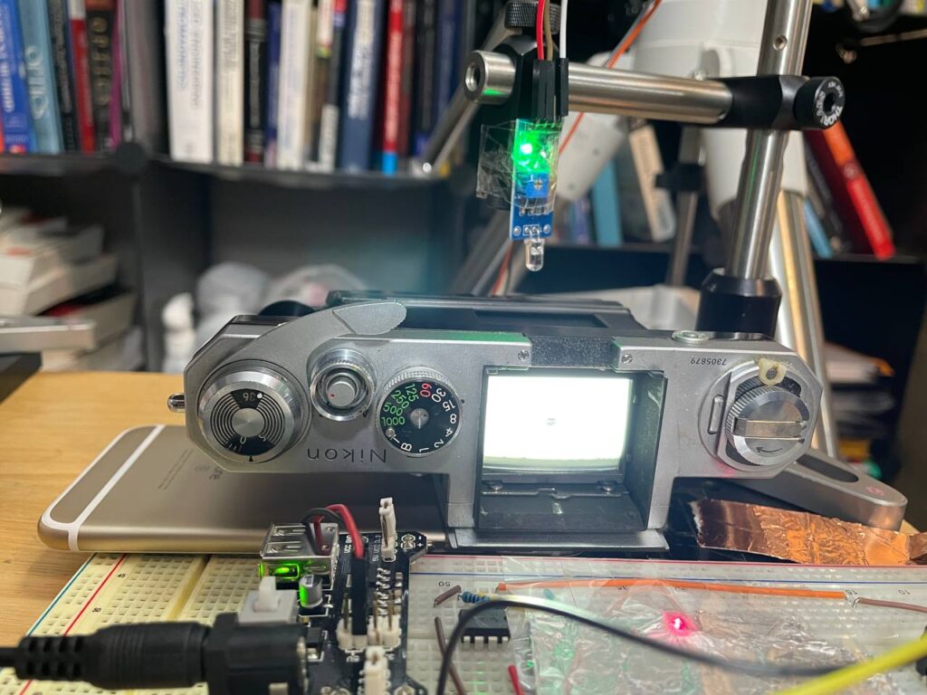
Figure 4 The schematic diagram of setup 1.
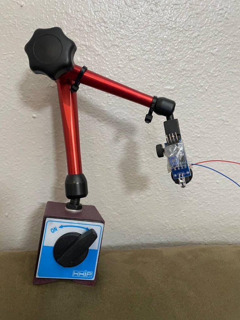
Figure 5 Using a magnetic base clamper for positioning the light sensor module.
Based on the data sheet, this component has a Propagation delay time of 1.3 µs. The typical response time for a photodiode is usually less than 1 µs. Therefore, this device is capable of achieving the characterization of camera shutter of at least 1/10000 or even higher. Therefore, the overall system ability to character the shutter speed is highly limited by the sampling rate of the data acquisition device, which is 48kHz for NI6009. With such data, in a rough estimation, it can accurately characterize a pulse signal of 0.5 ms (24 data points) or even 0.25 ms (12 data points) if the noise is low enough to accurately locate the rising edge and falling edge. Considering that the typical highest speed of a mechanical film camera is 1/1000 (1 ms)for focal plane shutter and 1/300 (3.33 ms) for leaf shutter, this setup is more than enough for this task.
The cost of this setup is also summarized as below:
- Light sensing module: about 3-5 dollars.
- Power source of 5V 1A: about 5-10 dollars on amazon.
- Breadboard, wire, small power module: less than 10 dollars, can also be obtained from an electronics basic kit, such as this one on amazon: https://a.co/d/6dgQCaZ.
- NI6009 data acquisition device: I bought mine for 27 dollars from eBay in 2025, same device can be easily found with prices less than 40 dollars.
- Magnetic base clamper (alternative): about 20-30 dollars on amazon.
2.3 Setup 2
In the setup 2, a laser diode was applied as the light source and a photodiode of PD638C was used as the light sensing device. To enhance the light signal and thus the SNR(signal-to-noise ratio), an operational amplifier (LM358P) was used in the circuit. The IN- leg was connected to a 10K Ω resistor and then to ground. The output leg was connected with a 1M Ω resistor and then to the IN- leg for the feedback. The cathode of the PD638C was connected to the IN+ leg of the LM358P. A photo of this setup is shown in Figure 6. The laser diode is at the left side, the operational amplifier and the power is on the breadboard. The circuit was covered by a shield made from tin foil (connected to ground) to prevent electrical interference from the coupling effect from the metal camera body and human hand.
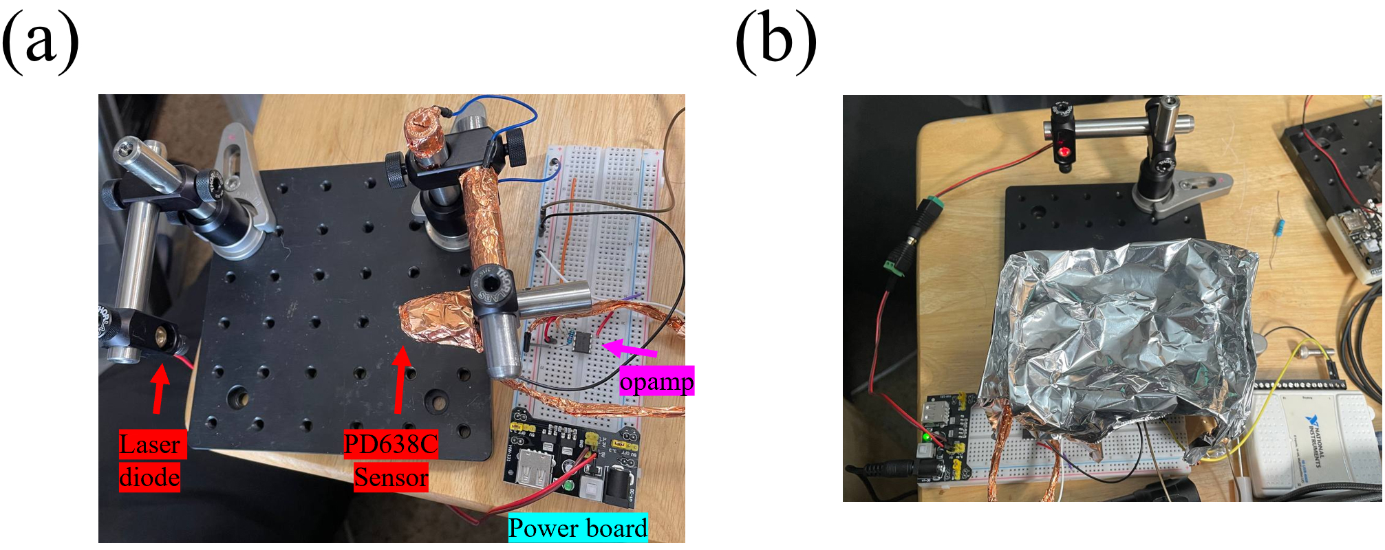
Figure 6 Photo of setup 2: (a) without tin foil shield, (b) with tin foil shield
The LM358P is a single power operational amplifier, making it quite convenient for being used on a breadboard since only a 5V power source identical to setup 1 is needed. It has a settling time of 4 µs with a 5V power supply and a slew rate of 0.5V/µs, making it capable of fully responding to an input in less than 10 µs if the output is less than 5V. The rising edge and falling edge of PD638C is 50ns/50ns, making its total response time well below 1 µs. Therefore, it’s safe to assume that such a setup is much more than enough to measure at least 1/100000 shutter speed. Therefore, just like in setup 1, the overall testing ability is limited only by the sampling rate of the data acquisition device and has no problem for measuring 1/1000 shutter speed.
About the cost, the laser diode can be obtained from amazon for much less than 10 dollars, the LM358P can also be purchased from amazon as 7 dollars for a box (50ps). The other parts and components such as power source and wire are similar to that of setup 1.
3. Some results and discussion
3.1 Setup 1
Two cameras were tested by setup 1: Nikon F and Nikon FT. Figure 7 and Figure 8 show 2 examples of the raw data. It can be seen that when testing high speed shutter such as 1/1000, the rising edge and fall edge was not very sharp. The main reason for this is that the photodiode is not at the same plane of the focal plane, causing an effect similar to the shutter efficiency, as discussed in section 1. Another possible reason for this phenomenon is that when the shutter speed is high, the size of the slit of focal plane shutter is small, causing diffraction fringes which produce signal on the light sensor even if the slit is not directly aligned with the photodiode. The photodiode itself also has a receiving angle about 30° – 60°, which also makes it picking up signals when the slit is not aligned with it. This effect can be mitigated by carefully selecting the beginning point and ending point of the shutter time so that only the time period during which the slit is aligned with the photodiode is included, as indicated in Figure 7. Another solution is using highly collimated beam with small spot size as the light source, such as the laser beam applied in setup 2. In figure 8, it can be seen that as the shutter speed reduce, the rising edge and falling edge of the signal becomes increasing sharp. Therefore, the beginning point and ending point can be just selected closed to the edge. Although the determination of beginning point and ending point can cause error, it’s roughly estimated that the error could be at most 5% – 10% of the total time period and might not cause a significant damage to the measurement results.
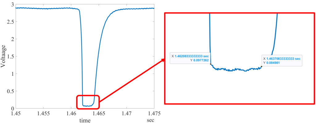
Figure 7 The raw data of 1/1000 shutter speed testing results from my Nikon F using setup 1
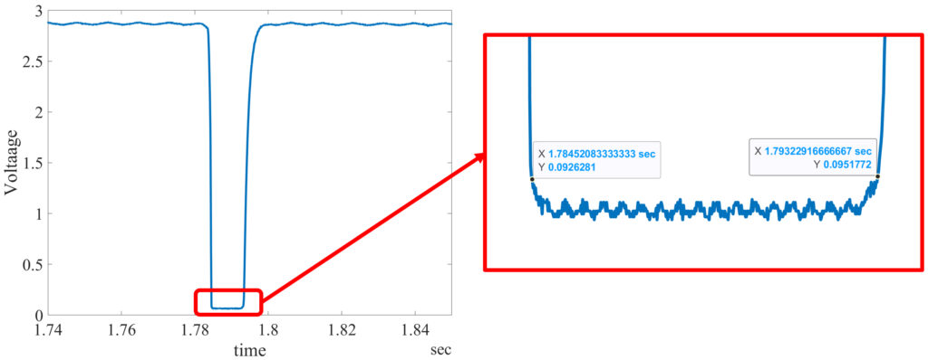
Figure 8 The raw data of 1/125 shutter speed testing results from my Nikon F using setup 1
The measurement results using setup 1 is shown in Table 1. It can be seen that the error is much higher in high speed shutter (1/1000 and 1/500). The shutter speeds in medium range, such as 1/125-1/8, are quite accurate. However, the error increases again for low shutter speed such as 1/4 and 1/2. Based on the information provided in [8], the 2 cameras being tested mostly fit with the DIN 19015 Tolerance limits and ASA tolerance limits, except the 1/1000 stop of both cameras and 1/4, 1/125 stop of my Nikon FT. These 2 standards allow relative error roughly about -20% to +20%. For higher standard such as Carl Zeiss manufacturing standard which never exceed 20% relative error tolerance, both of them might not be considered to be up to standard. This is expected since both cameras were purchased from eBay and might not have received any service for decades. Most of shutter is slower indicates issues related to lubrication and loss of stiffness in the spring. Based on the testing results, it’s safe to conclude that these 2 cameras can shoot ordinary color negative films without much exposures issues. It’s only when color slide film or other high-end light sensitive films are used that these shutters can cause potential problems.
Table 1 The measurement results using setup 1
| Nikon F | Nikon FT | |||
| Shutter speed | Measured time (ms) | Relative error (%) | Measured time (ms) | Relative error (%) |
| 1/1000 | 1.50 | +50.0 | 1.50 | +50.0 |
| 1/500 | 2.44 | +22.0 | 2.30 | +15.0 |
| 1/250 | 4.42 | +10.5 | 4.07 | +1.75 |
| 1/125 | 8.70 | +8.7 | 10.29 | +28.6 |
| 1/60 | 16.67 | 0.0 | 16.82 | +0.9 |
| 1/30 | 33.73 | +1.2 | 34.66 | +4.0 |
| 1/15 | 67.81 | +1.7 | 63.31 | -5.0 |
| 1/8 | 126.02 | +0.8 | 123.04 | -1.6 |
| 1/4 | 249.81 | -0.8 | 323.60 | +29.4 |
| 1/2 | 433.40 | -13.3 | 576.92 | +15.4 |
3.2 Setup 2
The setup 2 used collimated laser beam with very small beam spot (about 1 mm diameter), the rising edge and falling edge of the signal is expected to be much stepper. 4 cameras were measured: Nikon F, Nikon FT, Pentax sp2 and Fujifilm stx-1. An example of the raw data is shown in Figure 9. It can be seen that by using the laser as light source the rising edge and falling edge of the signal became quite sharp even for the 1/1000 shutter speed. The beginning point and ending point were selected near the edge. It’s worth mentioned that the pulse which supposed to be a rectangle signal was actually not flat on top, but contained a sinusoidal component with an amplitude of about 0.02 V. This component was believed to be noise from the DC power source connecting to the laser diode and thus modulated its intensity. Although such effect can cause some problem in selecting beginning point and ending point, this effect was estimated to be no large than 5% of the results.
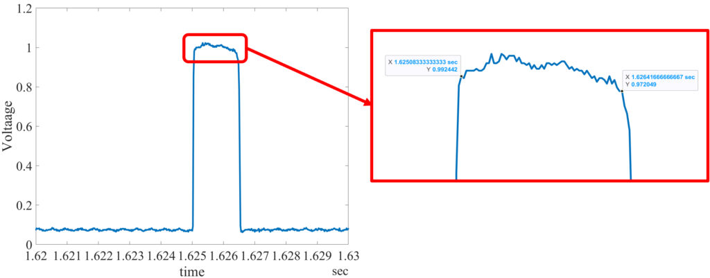
Figure 9 The raw data of 1/1000 shutter speed testing results from my Nikon F using setup 2
The measurement results of the 4 cameras are shown in Table 2. Comparing the Nikon F and Nikon FT results with that in Table 1, it can be concluded that, although the setup 1 has some issues and might not be as accurate as setup 2 as discussed above, most of the results from 2 setups are quite consistent. Both measurements revealed that 1/1000 stop for both cameras and the 1/125 stop of Nikon FT are much slower. However, for 1/4 stop of Nikon FT, the setup 2 provided a quite different result. The discrepancy might be resulted from some random error caused by either the procedure or the device. The Pentax sp2 showed a much slower speed in most of the stops, indicating the last owner might not quite care his gear. The Fujifilm stx-1 showed a surprising accurate shutter result, which might be due to the fact that this camera was manufactured much more recent than the others.
Table 2 The measurement results using setup 2
| Nikon F | Nikon FT | Pentax sp2 | Fujifilm stx-1 | |||||
| Shutter speed | Measured time (ms) | Relative error (%) | Measured time (ms) | Relative error (%) | Measured time (ms) | Relative error (%) | Measured time (ms) | Relative error (%) |
| 1/1000 | 1.33 | +33.0 | 1.43 | +43.0 | 1.60 | +60.2 | / | / |
| 1/700 | / | / | / | / | / | / | 1.71 | +19.7 |
| 1/500 | 2.60 | +30.0 | 2.15 | +7.5 | 2.56 | +27.9 | 2.14 | +7.3 |
| 1/250 | 3.85 | -3.8 | 3.90 | -2.5 | 4.61 | +15.3 | 4.20 | +5.1 |
| 1/125 | 8.69 | +8.6 | 10.02 | +25.3 | 8.64 | +8.1 | 8.33 | +4.2 |
| 1/60 | 16.81 | +0.8 | 16.50 | -1.0 | 20.52 | +23.1 | 16.89 | +1.4 |
| 1/30 | 33.67 | +1.0 | 34.29 | +2.9 | 40.71 | +22.1 | 31.07 | -6.8 |
| 1/15 | 69.41 | +4.1 | 65.10 | -2.3 | 74.94 | +12.4 | 61.86 | -7.2 |
| 1/8 | 124.50 | -0.4 | 124.49 | -0.4 | 130.29 | +4.2 | 105.23 | -15.8 |
| 1/4 | 239.83 | -4.1 | 285.57 | +14.2 | 257.81 | +3.1 | 265.63 | +6.3 |
| 1/2 | 449.12 | -10.2 | 589.63 | +17.9 | 499.52 | -1.0 | 508.40 | +1.7 |
4. Conclusion and future work
In this work, 2 solutions for accurately measurement of mechanical film camera shutter speed were proposed and demonstrated. The cost for either method is well less than 100 dollars, which makes them more economical than buying a commercial device of similar capability. Also, there is no need for building complicated mechanical structure and electronic circuit, which makes them very friendly to people who have no much space and gear for doing the DIY. The setup 1 is easier to implement than setup 2, since all the devices are available and even the breadboard circuit work is not needed except for the power board. Once its optical behavior and limitation is understood and addressed, this setup can provide very close results comparing with the setup 2.
In the future, to make the setups easier to use, the sampling device can be replaced with esp32. The detection of rising edge and falling edge as well as the results calculation can be automatically conducted by the esp32 and output on a screen. More cameras are going to be tested.
Reference
[1] Neblette. (2023). Photography: Its materials and processes. Legare Street Press.
[2] Katz, A. H. (1949). Camera shutters. Journal of the Optical Society of America, 39(1), 1-21.
[3] Simon, G., Vakulya, G., & Rátosi, M. (2022). The Way to Modern Shutter Speed Measurement Methods: A Historical Overview. Sensors, 22(5), 1871.
[4] Arild Edvard Båsmo. (2022, Jan 24). 5 levels of shutter testing: How accurate is your film camera? Kamerastore. https://kamerastore.com/en-us/blogs/posts/5-levels-of-shutter-testing-how-accurate-is-your-film-camera
[5] Tony Warren. (2023, May 24). A DIY shutter speed tester. 35mmc. https://www.35mmc.com/24/05/2023/a-diy-shutter-speed-tester/
[6] mattthegamer463. (n.d.). Build a camera shutter speed timer. Instructables. https://www.instructables.com/Build-a-Camera-Shutter-Speed-Timer/
[7] Lommen, J. (n.d.). Technical – Jolo Medium Format Camera. Jolo Cameras. https://jolommencam.com/technical/index.html
[8] Alvandi Camera Systems. (2020, May 22). Alvandi shutter speed tester. ALVANDI CAMERA SYSTEMS. https://www.mr-alvandi.com/technique/Alvandi-shutter-speed-tester.html
Share this post:


Comments
Bob Janes on Camera shutter testing device based on photodiode sensor and data-acquisition device
Comment posted: 03/08/2025
Having a laser light source, with a very small point of light must make things a good deal more accurate. Assuming that quartz-timed shutters are going to be more accurate, could one of those be used one of those as a reference?
At the end of the day, the key thing is that the negative gets the right exposure, so as long as you get consistent results as the speed goes up, things should be OK - ie I woundn't worry about what shutter speed is actually being used unless it starts to affect results...
Having said that, there is a lot to be learned in measurement. Being a bit of a fan of optical measurement, I think I would favour photographing something moving at a known speed and measuring the blur.
Comment posted: 03/08/2025
Gary Smith on Camera shutter testing device based on photodiode sensor and data-acquisition device
Comment posted: 03/08/2025
Most of this seems to have been written for submission to a journal targeted at individuals who have skills far beyond mine.
Comment posted: 03/08/2025
Roger on Camera shutter testing device based on photodiode sensor and data-acquisition device
Comment posted: 03/08/2025
I have thought about buying a PhotoPlug to test some old cameras but decided I did not need it, for reasons similar to Gary Smith’s. Because I use only B&W film, over/under exposure is usually the result of user error (aside from one camera where the slowest shutter speeds are so far out that it is obvious from the sound of the shutter).
Comment posted: 03/08/2025
Comment posted: 03/08/2025
CHRISTOF RAMPITSCH on Camera shutter testing device based on photodiode sensor and data-acquisition device
Comment posted: 05/08/2025
Comment posted: 05/08/2025