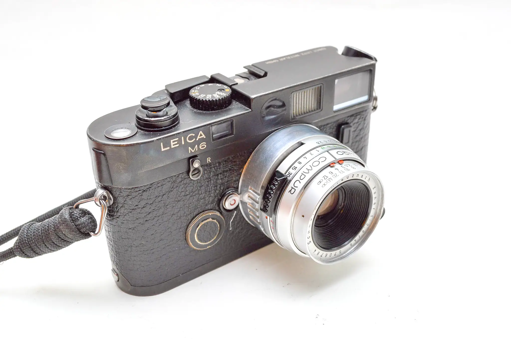
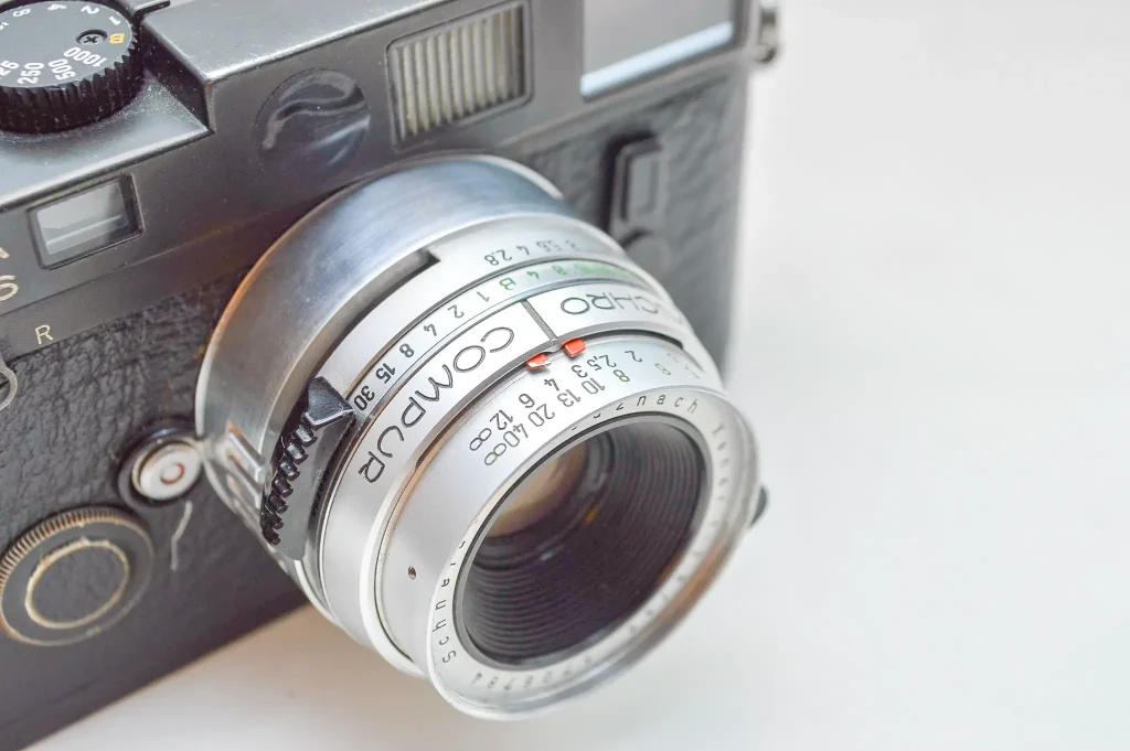
I’m Ellis, I study Mechanical Engineering in southwest England and enjoy working with analog cameras and various other things in my spare time. After completing a couple of Leica lens conversions – one of which Hamish reviewed here – I had a request from my friend Ollie to look into some possible donor cameras he had to make a new conversion.
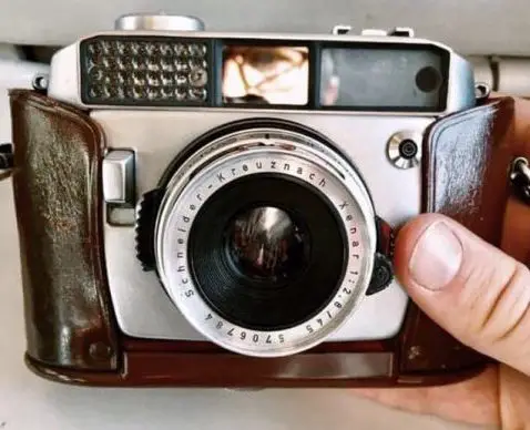
The final lens can be seen above, but the pre-existing parts and optics came from a Balda Baldamatic II; a German rangefinder manufactured from 1958-1962. This version sported the Schneider Xenar 45mm f/2.8; a surprisingly sharp lens with sliding DOF scale markers, similar to some Hasselblad lenses.
The lens is hand machined from aluminium alloy, using a small modelmakers lathe/mill I recently acquired over the summer. Below I will show how the lens was conceived and the resulting images from it, shot on my M6.
All of my conversions start by taking the camera apart for an initial investigation to see if it can possibly be used. In this case the lens could be removed with several screws due to the relatively simple mechanics of the camera. When choosing lenses to adapt, the critical factor is having enough space in the pre-existing design to add parts for the conversion. The Xenar lens sits over 10mm further forward than the M-mount so there is plenty of space for an adapter.
The next to step is to look at the possibility of adding a rangefinder coupling to a lens – the design of the pre-existing parts of the lens are critical here. In order to add the coupling, there must be a rotating ring at the rear of the lens to which a coupling ring can be fixed and calibrated for the given focal length. The ring has to rotate as almost no lenses are equal to the datum Leica focal length of 51.6mm, this is the actual focal length of all 50mm Leica mount lenses and is the only focal length that does not require a rotating rangefinder coupling. This particular lens is focussed using the front element group, meaning there is no way to connect the mechanism to the rangefinder for coupling at the rear, hence the lens is strictly zone focus.
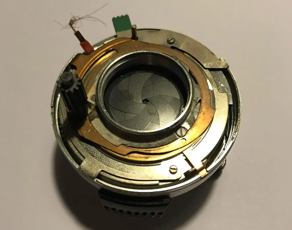
After deciding a lens is suitable for a conversion, it is completely stripped down, cleaned and put back together using only the necessary parts. This usually this means removing the whole shutter mechanism. I also lubricate all necessary areas and make the aperture as smooth as possible.
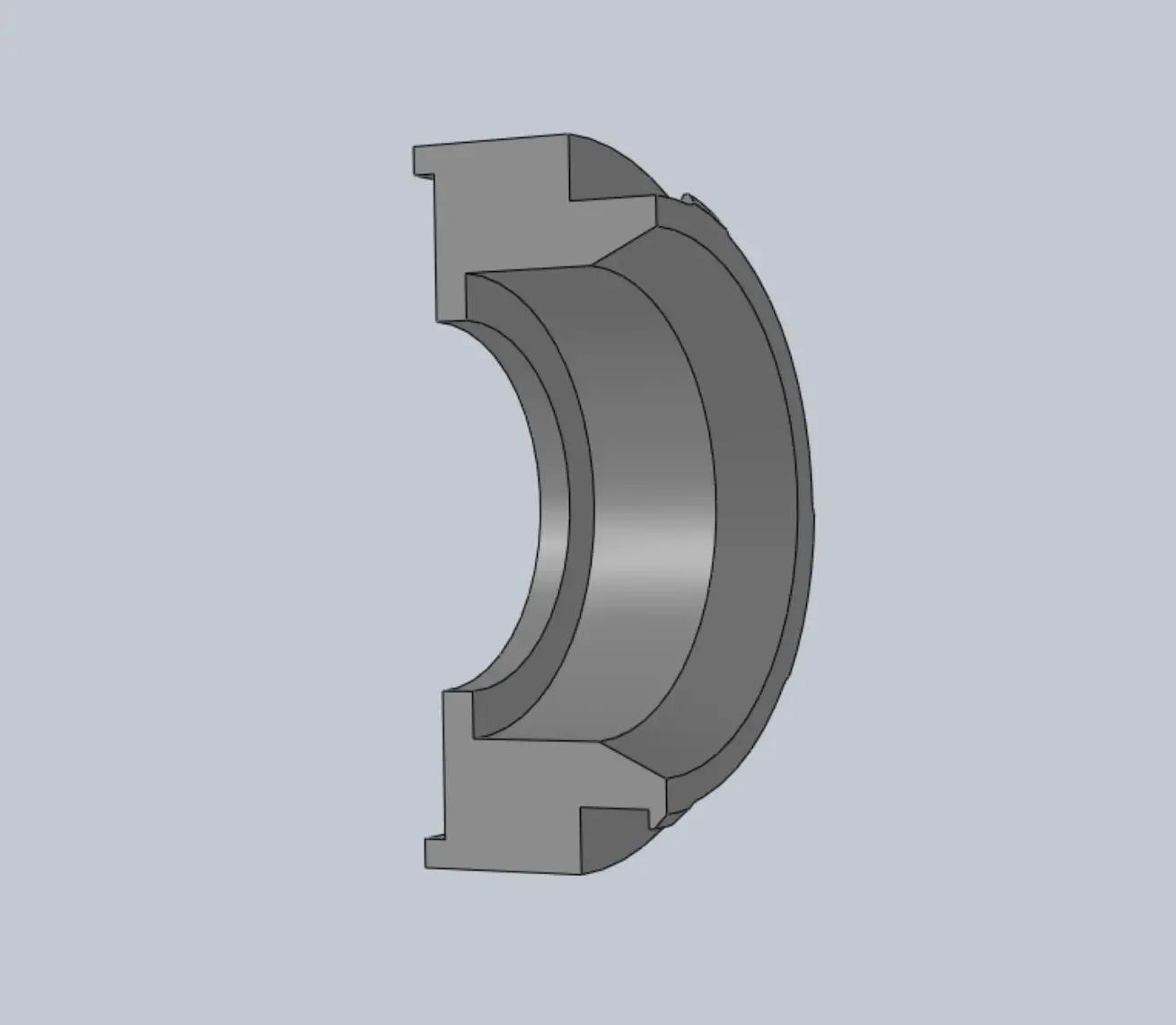
During the disassembly process I’m constantly taking rough notes on dimensions, important mechanisms etc. which will determine the basic nature of the parts needed to make the conversion happen. Here the critical dimensions are the distance between the body and lens, as well as the male thread around the rear element, that was to be used to fix the adapter to the lens. The next step is to create a computer model, here only one 3D file is required however for more complicated, coupled lenses, I would recreate the whole mechanism to get a better view of how everything fits and operates together.
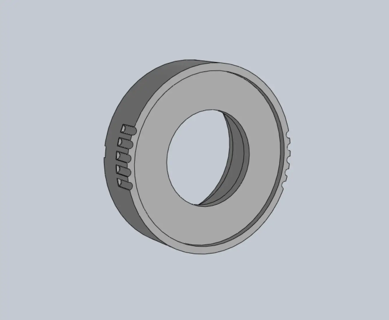
I start with a master file which contains my m-mount design, adding the necessary features to make the lens fit, for this adapter I also added some grooves which add some detail to the otherwise plain cylindrical shape between the lens and camera, aiming to avoid the look of an out of place adapter.
With the design being completed and checked over, the manufacturing stage can begin. 3D printing is viable with some high end stereolithography printers, however there will always be small imperfections with parts which require such fine details. Because of this I spent some time looking for a small lathe.
The adapter started as an unfinished wheel bolt, for our university race car.
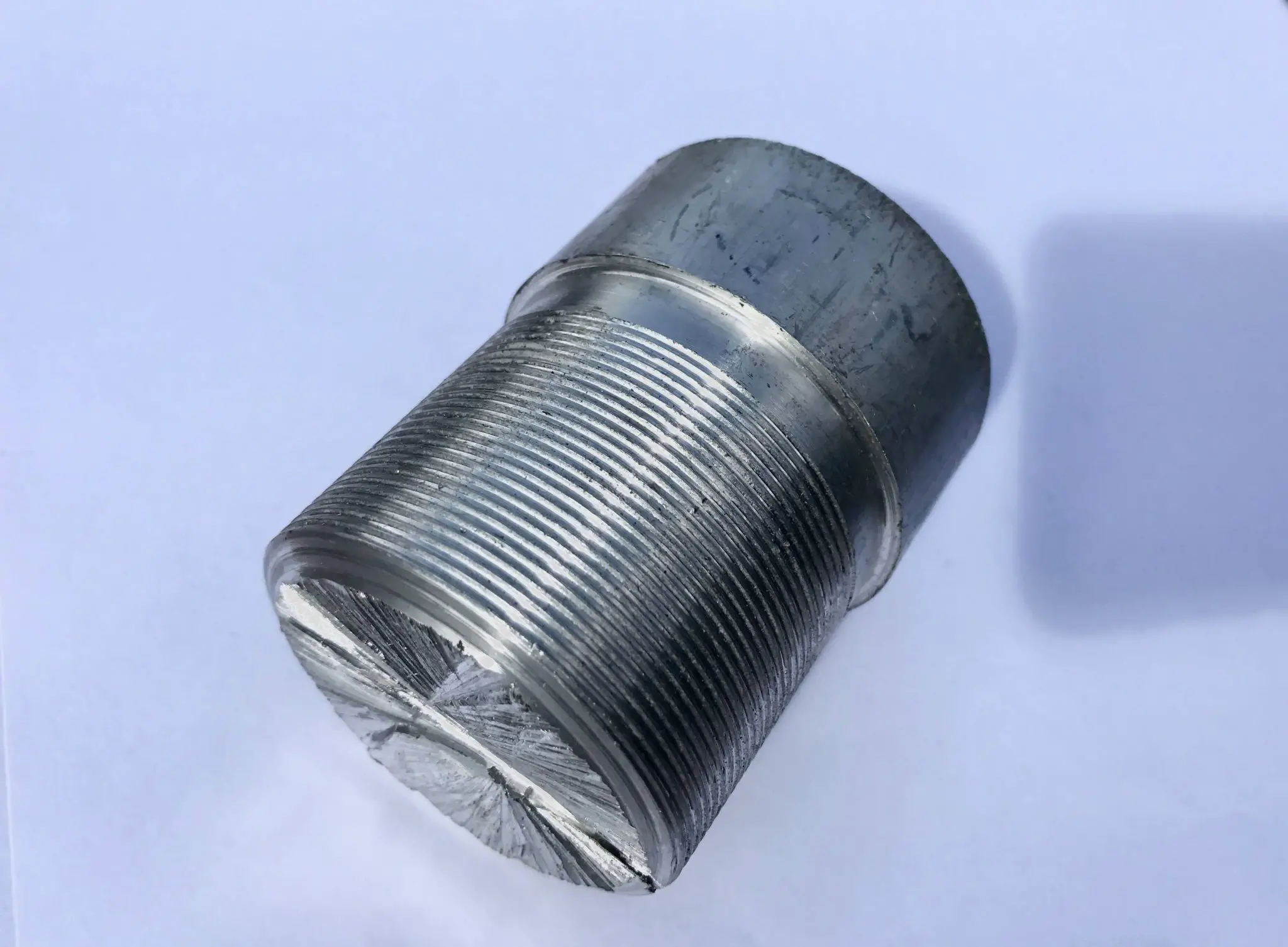
Since my lathe is so small it had to be cut down by hand to fit the chuck, the chuck being a chunk of steel that holts the part in place on the lathe.
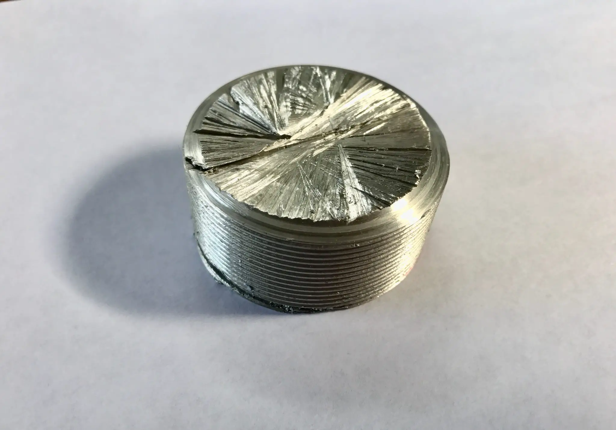
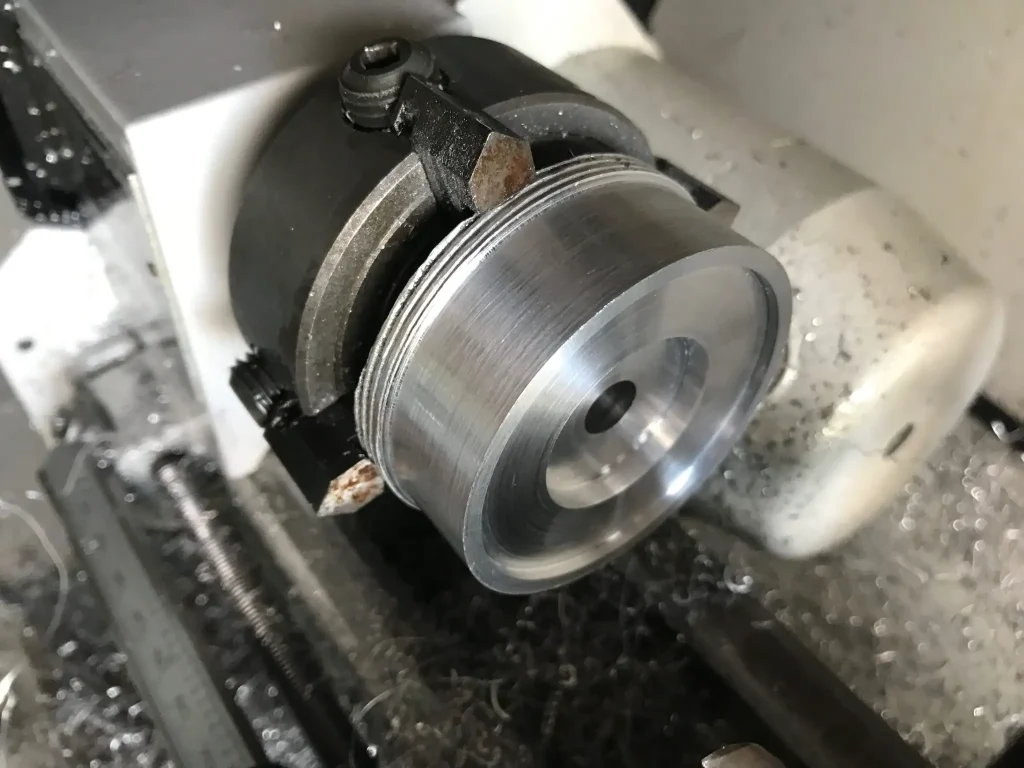
The part was then fixed into the chuck and metal cut away to leave a rough shape of the part.
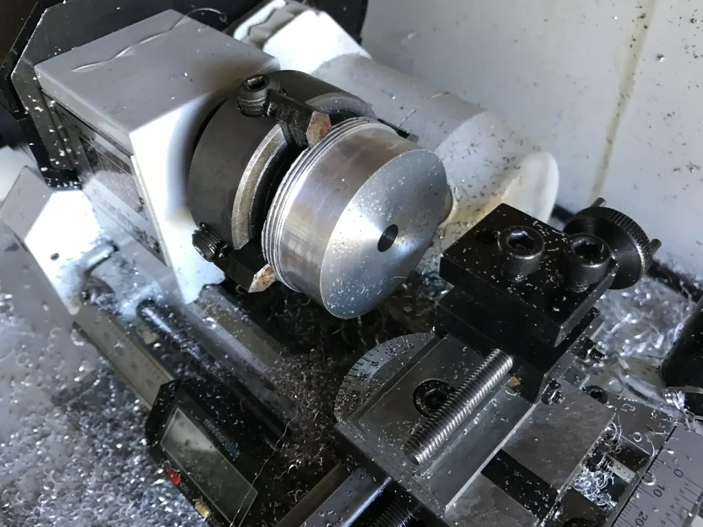
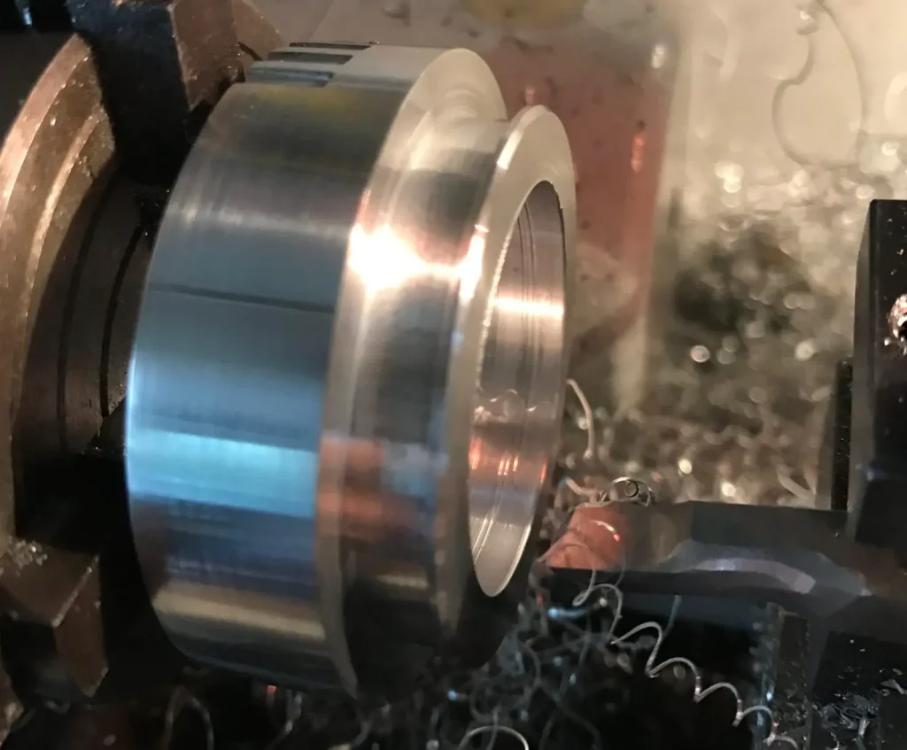
Here the adapter is seen from the front, the thread on the lens unit sits inside the central bore (seen in the part above) and is fastened from the rear with the locking ring. Since the outer barrel of the lens is finished here, it is polished using the lathe, which is much faster than polishing by hand.
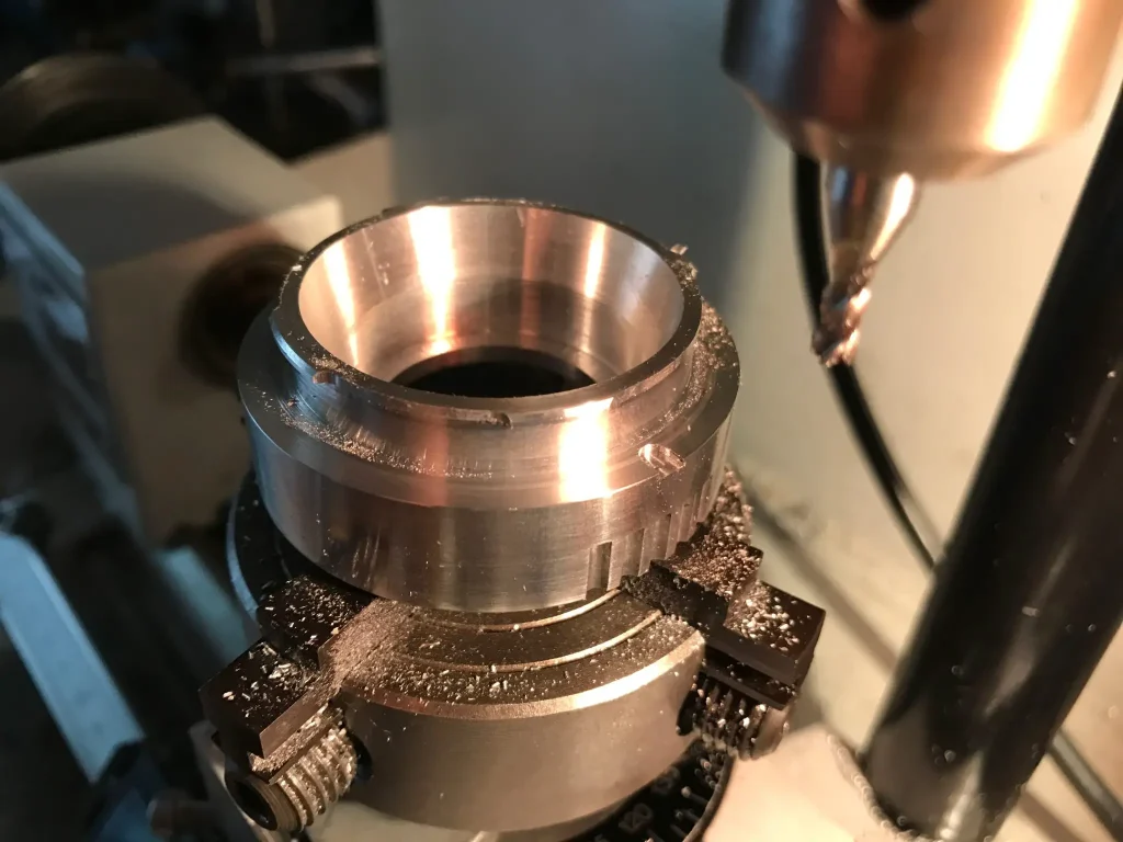
Having finished machining the front of the lens, it is reversed and the rear is machined to leave the basic m-mount flange.
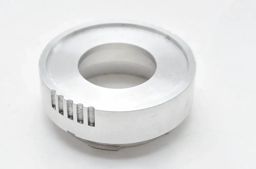
To complete the mount, the flange is cut on a milling machine to leave flanges of specified lengths. One flange must be machined to an exact length to determine which frame lines are selected by the camera. A recess is also machined which will provide the locking function of the lens when it is mounted. Here you can see the completed m-mount:
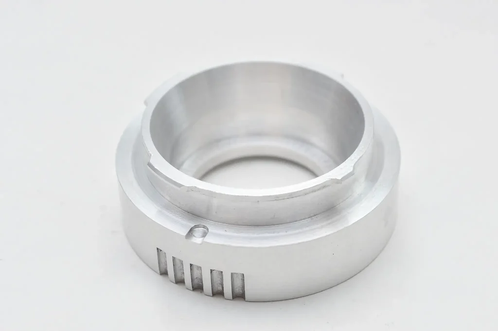
The final adapter piece – it weighs around 40g without the lens unit. Note the grips around the lens, these will allow the lens to be removed easily and break up the flat, basic design of a simple cylinder.
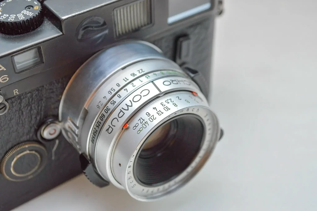
The completed lens:
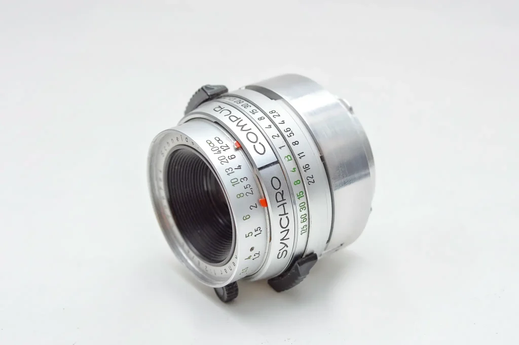
Here you can see the moving depth of field markers on the lens. These move smoothly with the aperture ring – it’s a very well executed feature which I would like to have seen on more lenses.
Here are some test images from the lens, shot on my M6 with HP5+ pushed to 1600.

This conversion was a relatively simple, single component design. The hard part was getting hold of the equipment to manufacture it. Overall I am very happy with the lens, namely the aesthetics and ergonomics. I am also pleasantly surprised at the sharpness of the lens.
If anybody reading this feels inspired to try out something similar, all you need is some screwdrivers and some free CAD (Computer Aided Design) Software, which can be learnt very quickly and be used in endless applications. 3D printing is very cheap and accessible manufacturing method and is a great way to prototype designs, the only downside being aesthetics. That being said, it is definitely possible to achieve good results with some good post-processing.
This is the 4th lens I have converted for Leica, the previous being from a Minox 35, a Rollei 35B and a Yashica Electro. I am also working on designs for new lenses during my spare time at University. For anybody interested in the lenses or help on their own designs please contact me via email, or message my Instagram account, where I regularly post updates of what I’m working on.
Thanks for reading everyone.
el******@***il.com
www.instagram.com/f1.420/
Share this post:


Comments
Alexander on Schneider 45mm f/2.8 Xenar to Leica M mount Conversion – By Ellis Ley
Comment posted: 16/10/2018
Just one thing: please, it should always read SCHNEIDER with *ei* :D
Comment posted: 16/10/2018
Daniel Castelli on Schneider 45mm f/2.8 Xenar to Leica M mount Conversion – By Ellis Ley
Comment posted: 16/10/2018
Comment posted: 16/10/2018
raygoodwinphotos on Schneider 45mm f/2.8 Xenar to Leica M mount Conversion – By Ellis Ley
Comment posted: 16/10/2018
Bent_Brent on Schneider 45mm f/2.8 Xenar to Leica M mount Conversion – By Ellis Ley
Comment posted: 17/10/2018
This is awesome. If you do more, please keep sharing. Really cool and really interesting.
Edmund Hawe on Schneider 45mm f/2.8 Xenar to Leica M mount Conversion – By Ellis Ley
Comment posted: 17/10/2018
StephenJ on Schneider 45mm f/2.8 Xenar to Leica M mount Conversion – By Ellis Ley
Comment posted: 17/10/2018
Comment posted: 17/10/2018
Laurence Liu on Schneider 45mm f/2.8 Xenar to Leica M mount Conversion – By Ellis Ley
Comment posted: 29/10/2018
Comment posted: 29/10/2018
Comment posted: 29/10/2018