There’s a scene in Jurassic Park where Dr. Malcolm (Jeff Goldblum) gives the park’s creators a lecture on ethics. He ends with the famous line, “Your scientists were so preoccupied with whether or not they could, they didn’t stop to think if they should.”
This post – part 3 of my Pinhole Adventures series – is about making, measuring and testing the “optimal” pinhole. There is a consensus on optimal shape (round pinholes produce the sharpest images), but what’s the optimal pinhole size? Surprisingly, the answer is not straightforward. Since I first became interested in this question, I’ve read a good deal of technical literature, and done my fair share of experiments. And I often found myself thinking about what Dr. Malcolm said. Perhaps, with the benefit of centuries of scientific research, we can potentially calculate and create optimal pinholes, but…
…Should we?
Granted, poking tiny holes in aluminium foil is not on the same level as unleashing rampaging dinosaurs upon innocent tourists. But mention “optimal diameter” on any pinhole photography forum, and you’ll inevitably get some people – let’s call them the pragmatists – saying “Don’t waste your time on theoretical claptrap, go out and take photos.” Or “Pinhole photography is not about sharpness.” Or “If you want sharp images, just use a normal camera.” At the other end of the spectrum, there are others – let’s call them the perfectionists – who will tell you, “Homemade ones will never be sharp enough, just buy a laser-cut pinhole.”
They both have a point, but I’m a big advocate of “whatever works for you”. And personally, I happen to fall somewhere in between. To the perfectionists, I’d say that I enjoy working with and testing the limits of homemade equipment and processes. There’s nothing wrong with buying laser-cut pinholes (or readymade cameras for that matter), but it’s a fun challenge to try and get sharp images, using nothing more than recycled materials and science. And I like doing home experiments, trying to see if my results match the theory.
I also agree with the pragmatists that pinhole photography is not about sharpness. In fact some of my first photos (which I quite like, if I may say so myself) were made with a pinhole which is far from optimal. But now that I understand how pinholes work, I feel like I have the freedom to make sharp or unsharp images depending on the effect or mood I want to convey – making a deliberate creative choice instead of an accidental one. (“Sharp” of course is a relative term. By normal photographic standards, even optimal pinholes make unsharp images.)
In a way, I am a bit envious of people who take a happy-go-lucky approach, unburdened by the desire for predictability and control, and somehow still end up with great images. Lomogoraphy has much in common with pinhole photography, and one of their golden rules is “Don’t think.” Or to quote Henry David Thoreau, “There is a certain perfection in accident which we never consciously attain.” Perhaps if he were alive today, Thoreau would be a lomographer. But for better or for worse, my personality type is different. Maybe that will change, someday.
TL;DR
I may as well be upfront: this is a technical post, based on many weekends of research and testing. (Subsequent parts of the series will be more reader-friendly, I promise.) I’ve tried to keep it interesting with photos and comparisons, but even so, I expect it will be of interest only to a small (or shall we say, exclusive) group of readers. Pinhole photography is already a niche pursuit. Among pinhole photographers, those who make their own pinholes, or care to measure or optimise them, are an even smaller niche. Nevertheless, I am one of them, and I wanted to put down in writing what that I learned from reading and experimenting, in the hope that it might help others like me.
There are three main parts to this post:
Part A: Making good-quality pinholes
Part B: Measuring pinholes
Part C: Optimal pinhole size
It is a long post, but depending on your goals, some parts may be more relevant than others. For example, let’s say you make your own pinholes (Part A), but couldn’t care less about “optimal size” (Part C). Measuring (Part B) is still potentially useful because it lets you determine the aperture, which in turn helps you decide how long to expose for (though if you’re not into measuring, you can also determine exposure by trial and error).
Or let’s say you buy your pinholes, so making (Part A) is not relevant to you, nor is measuring (Part B) because commercially-available pinholes come in specified sizes. But you might still be interested in optimal size (Part C), because if you’re looking for sharp images (which is presumably why you buy pinholes rather than making them), you’d want to know what size to get for your camera.
Anyhow, here’s an overview of what I cover. If you’re interested in a specific section, just click the relevant link, and feel free to ignore the rest.
Making pinholes
What material to use
Making “good” pinholes without specialised equipment
How clean are homemade pinholes?
Measuring pinholes
Four(!) different methods for measuring pinhole diameter
Comparison of the methods
Mounting pinholes on a digital camera
Finding the pinhole aperture
Optimal pinhole size
Scientific theory
Resolution versus contrast
Testing pinhole sharpness, and conclusions
A tool for calculating optimal pinhole size
Making pinholes
Soft vs hard pinholes
Pinholes are typically made from a thin, opaque material, and taped over a larger hole in the camera body – a bit like mounting a lens. There are two classic types of homemade pinhole. The first is a “soft pinhole”, made from materials like aluminium foil or gaffer tape. In Part 1, I described my process for making soft pinholes (photo below). Being faster and easier to make, I think they are a good choice for “starter pinholes” or when testing a camera.
The second type is a “hard pinhole”, made from a piece of thin metal. I now use hard pinholes almost exclusively. They are a little more effort to make, but are more durable than soft pinholes which can get damaged or frayed with use. In my tests, I also found that hard pinholes are slightly sharper, maybe because they can be sanded down (as described below).
Procedure
I make my pinholes from recycled soft-drink or beer cans. Beer-can walls are about 0.1mm thick. Some people use brass shims from hardware stores which can be as thin as 0.02mm. Generally speaking, thinner materials make better pinholes, but I’ve not tried brass shims yet, so I can’t compare. 0.1mm is still pretty thin though, and by sanding around the hole, you can make it even thinner.
I start by cutting the top and bottom off a can with a craft knife.
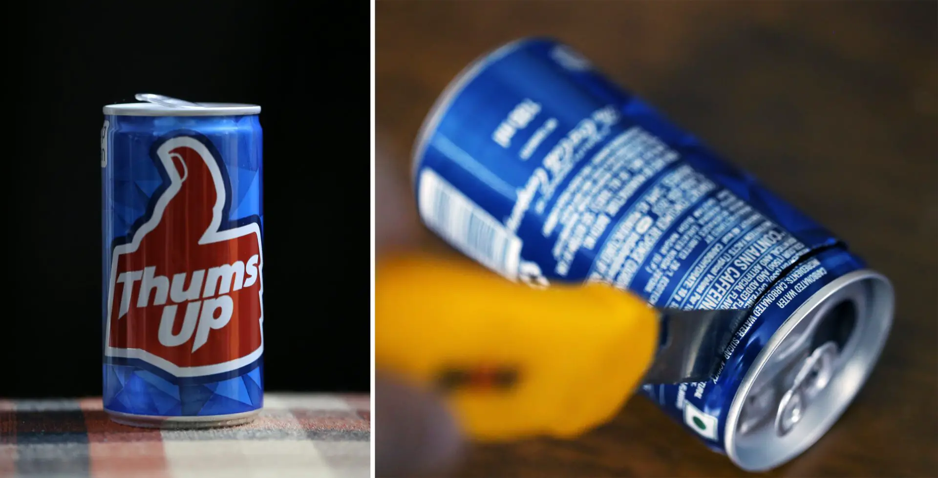
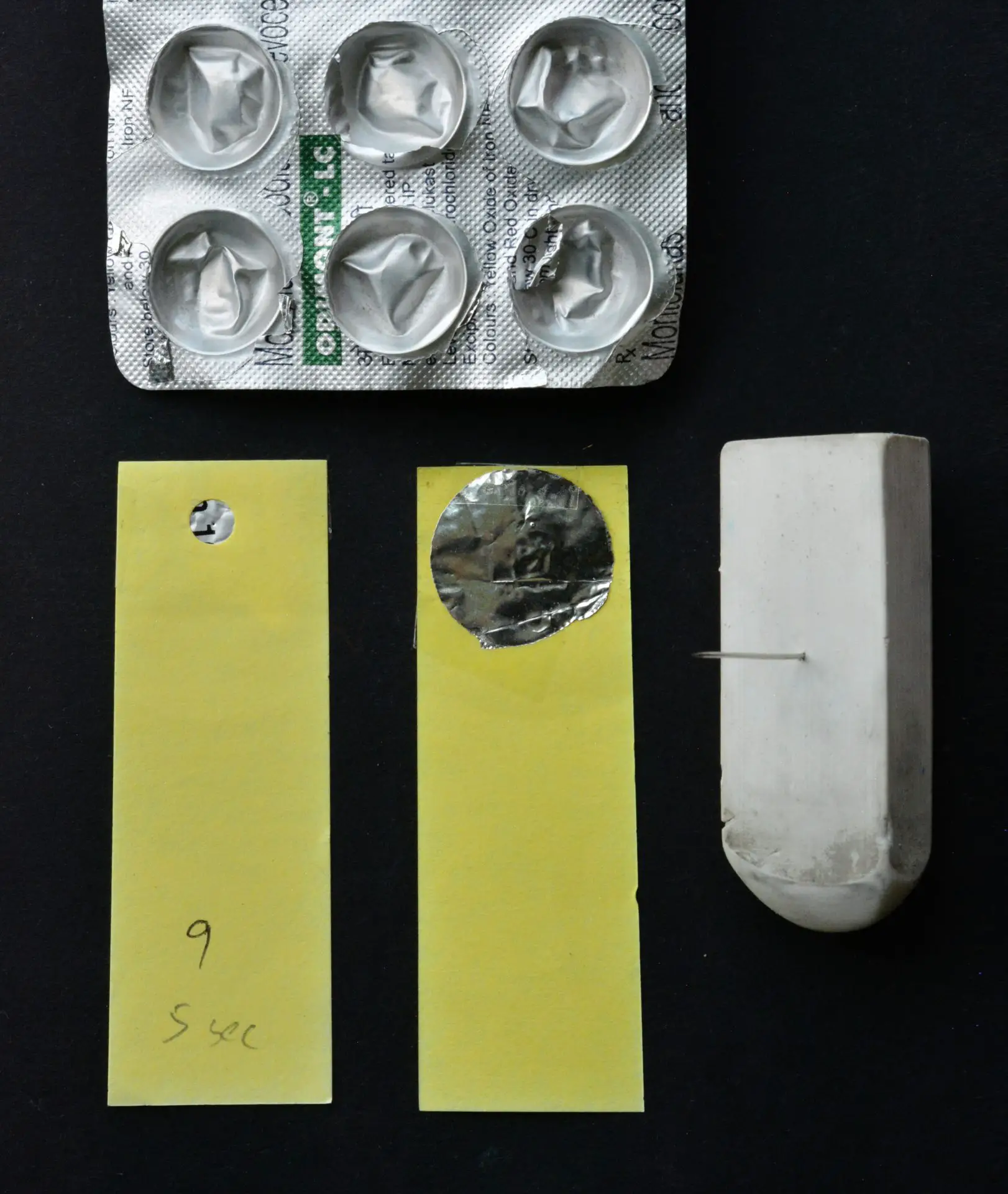
I then make a vertical cut in the wall to “unroll” it (below left), and cut it into 2×2cm pieces – one for each pinhole. To make the pinhole itself, I use a sewing-needle whose top is poked into an eraser for better grip (below right). I know other people who use the thinnest needles they can find, including micro-drills, entomological pins and acupuncture needles. But I try to work with what I already have, and I’ve made good pinholes as small as 0.15mm with sewing needles which are much thicker. The secret is to poke just the tip, and not press it all the way into the metal.
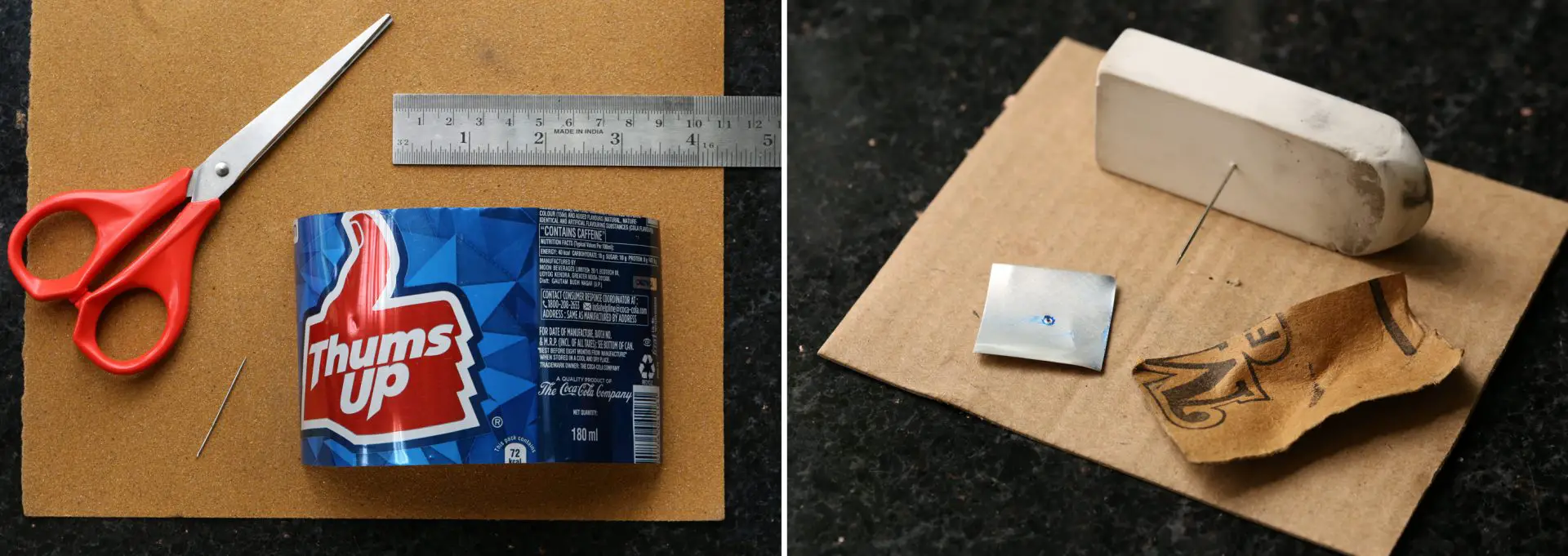
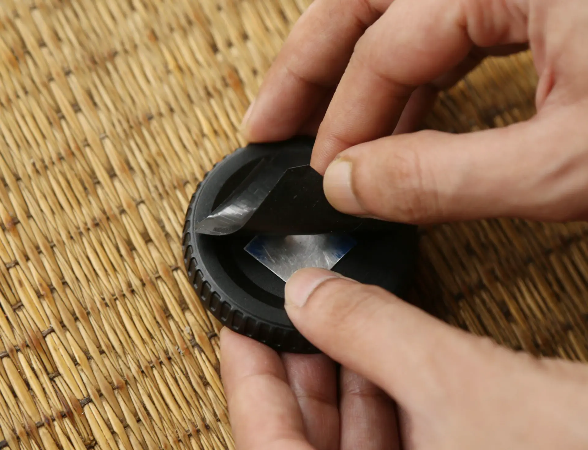
On a hard surface like a granite countertop, I place a thin piece of cardboard, and then the metal square on top. I then gently press the needle into the metal piece. Holding the needle steady, I turn the metal, as shown in the GIF below.
Some books and websites recommend not fully puncturing the metal – to stop when you see a burr on the other side, and sand it off to create the pinhole. This method doesn’t work well for me – I seem to end up with not-quite-circular pinholes (maybe my sanding technique needs improvement).
However, I’ve got good results from making a tiny hole in the metal with the needle tip (that is, puncturing it, but only just) and then sanding. Basically the tip should pierce the metal (Fig.1) but not go all the way in; that generally makes the hole too big. I then sand both sides with fine sandpaper, to remove irregularities and make the surface smooth (Fig.2).
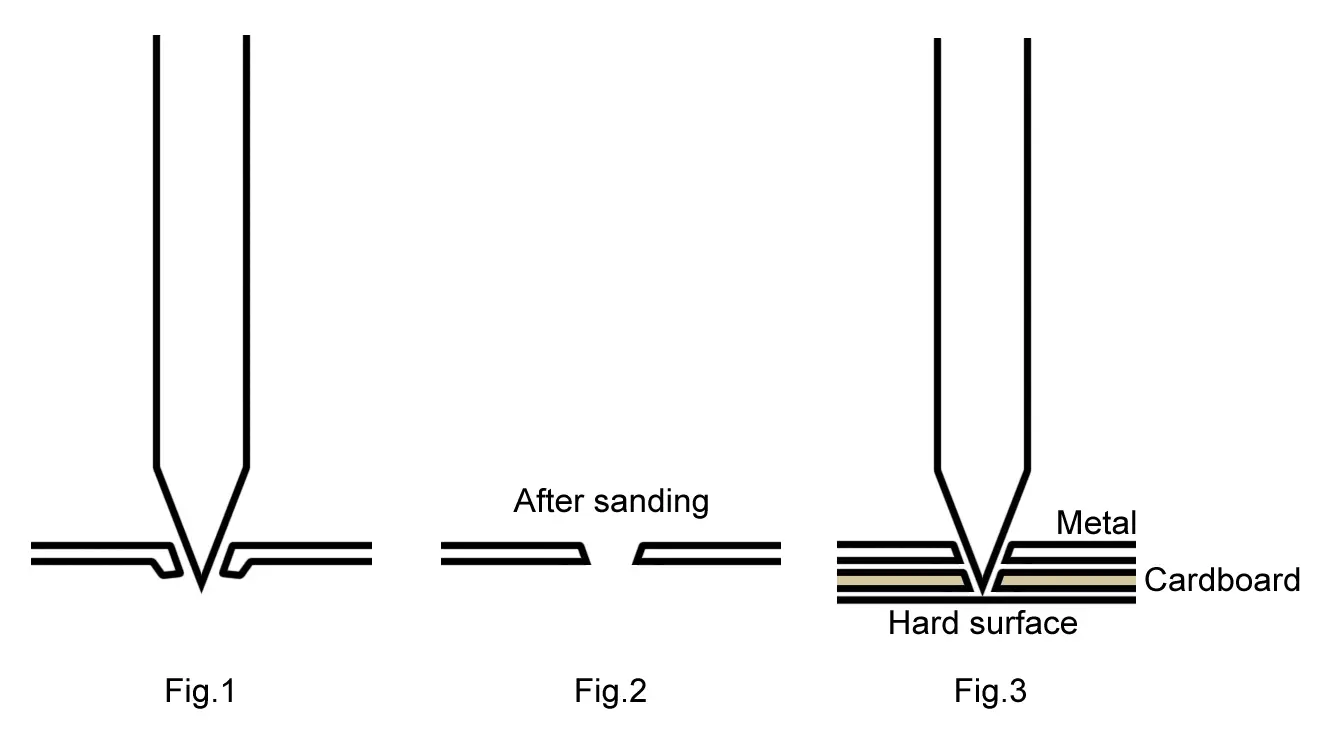
Obviously, the size of the pinhole depends on how far you push the needle in. You can control this to some extent by varying the thickness of the cardboard which you place under the metal. The needle goes through the metal as well as the cardboard (which acts as a spacer), but is stopped by the hard surface underneath (Fig.3 above).
For example, the sewing needle which I use (unknown size), when used with a cardboard spacer from a toothpaste box, creates a pinhole of around 0.25mm. I can make smaller holes by using thinner card or regular paper, and bigger holes by using more or thicker cardboard.
Finally, I number the pinholes. This is for easy identification when I subsequently measure and test them. I also “paint” around the pinhole with a permanent marker, to reduce reflections inside the camera. The ones shown below have not been painted yet. They have been sanded though; you can see the fine scratches.
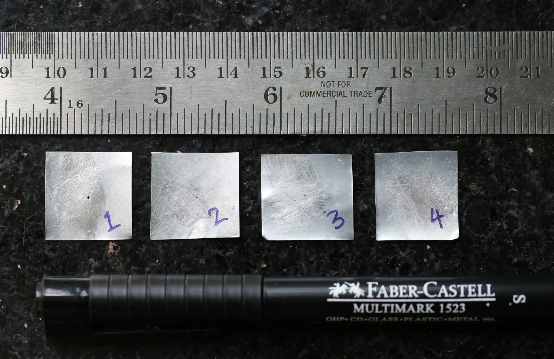
Results
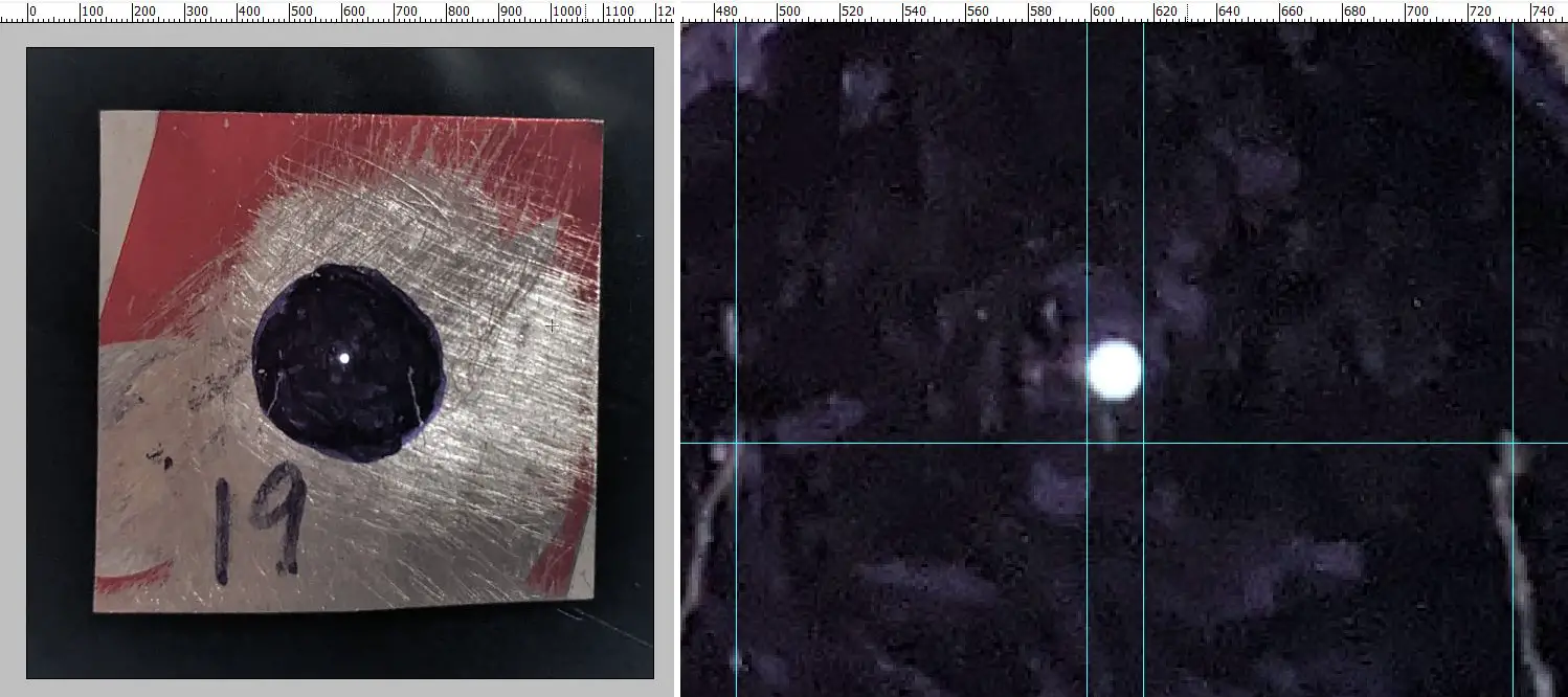
How good are homemade pinholes? For sharp images, you want circular pinholes with smooth edges. I don’t have laser-cut pinholes to compare, but pinholes made by the method described above are pretty clean, as you can see from the macro photos below. The first image below shows a 2×2cm piece of metal. The pinhole is at the centre (I painted around it to avoid reflections, as described above). The yellow square shows the approximate area which is magnified in the second image.
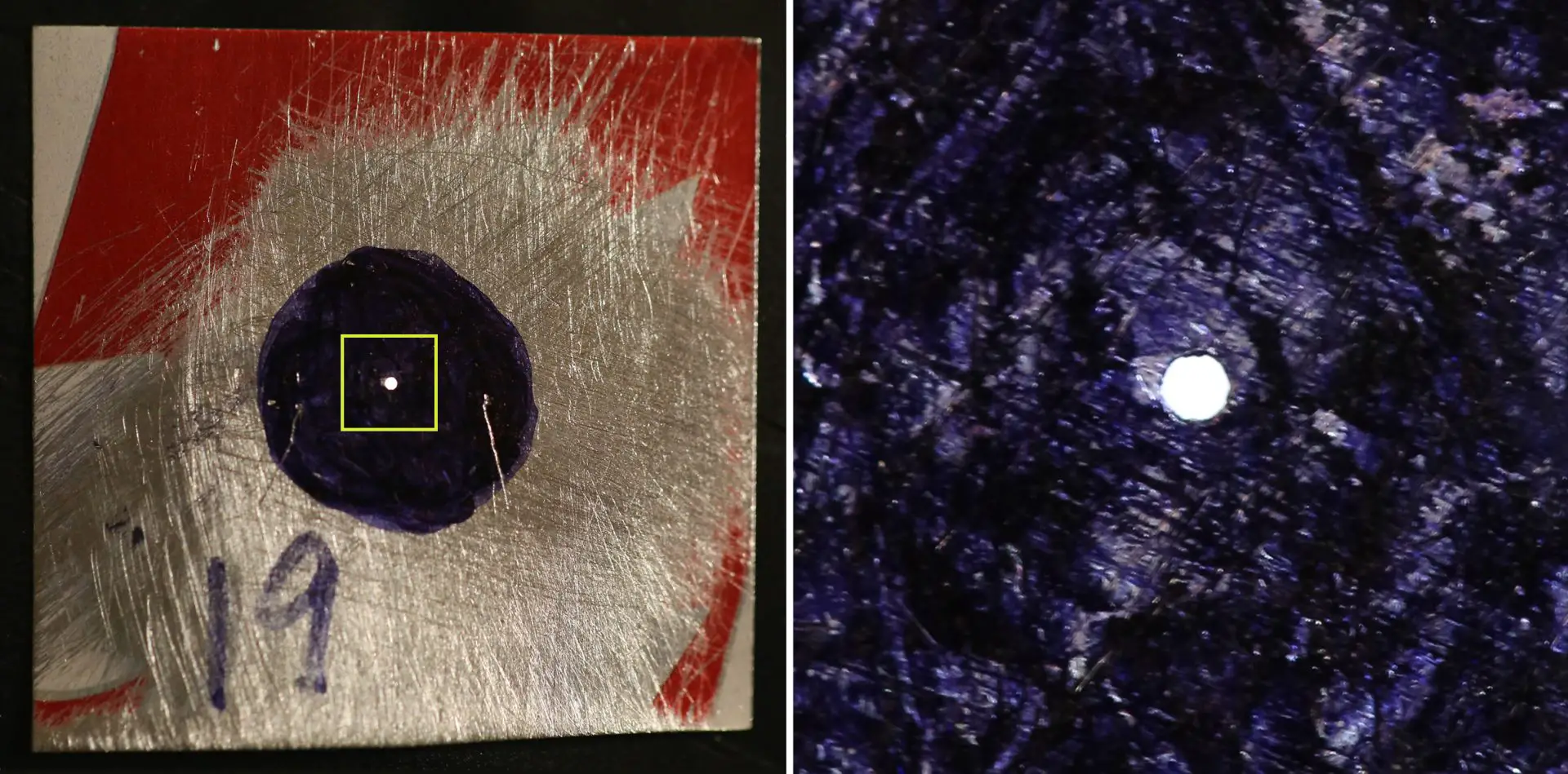
The images above are highly magnified; this particular pinhole has a diameter of only 0.33mm. How do I know? I measured it. Read on.
Measuring pinholes
After making a pinhole, my next step is to measure it. (In practice, I generally make several pinholes of different sizes, and then measure them all at once.) Measuring is useful both to determine the aperture, which in turn helps estimate how long to expose for. It’s also useful if you’re interested in making “optimal” pinholes, which I cover in the next section.
Everyone has their own favourite measurement method. In this section I’ll describe four different methods, including one (the “Exposure method”) which I haven’t seen anywhere else. I’ll demonstrate all four methods by measuring the same pinhole, and also compare their pros and cons.
Scanner method
For this method you need a flatbed scanner and an image editing program like Photoshop, or GIMP which is free and open source (I’ll use Photoshop as shorthand). The steps are as follows:
- Scan the pinhole at the highest possible resolution and open it in Photoshop.
- Increase the image size to 10x (i.e. 1000%).
- Change the Photoshop ruler units to millimetres.
- Draw vertical guidelines to “measure” the pinhole, and divide the result by 10 (since the image is 10x magnified, 1mm on the virtual ruler corresponds to 0.1mm in real life).
Below left is the scan. The pinhole is at the centre. I placed a piece of black paper above it for better visibility, increasing the contrast between the pinhole and the light-coloured metal around it. Below right, I opened it in Photoshop, magnified and drew vertical guidelines (cyan) on either side of the pinhole.
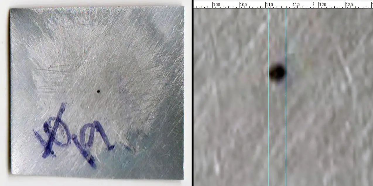
Some people seem to like this method, but it doesn’t work well for me. With my scanner, which maxes out at 600 dpi, small or medium pinholes like this one are not that well-defined. Anyhow, the guidelines look roughly 3.5mm apart according to the Photoshop ruler, so the pinhole diameter as measured with the Scanner method is 0.35mm.
Macro method
For this method you need a digital camera with a macro lens, a ruler, a needle, a source of backlight (like a phone screen), and Photoshop or similar software. The steps are as follows:
- Measuring carefully with a ruler, make two small, light scratches with the needle, exactly 5mm apart on either side of the pinhole. Take care not to pierce the aluminium. With the aid of these two “control marks” which are a known distance apart, we can measure the pinhole in Photoshop.
- Place the pinhole on a light source, like a phone or tablet screen, so that the light shines through. I set my phone screen to maximum brightness and go to WhiteDisplay.com. You’ll also need some light on the pinhole so as to see the control marks. (Instead of control marks, you can also lay a ruler next to the pinhole, but control marks are more precise since they are on the same plane as the pinhole.)
- Photograph the pinhole from directly above, at the highest possible magnification and resolution. Open the image in Photoshop.
- Rotate the image until the control marks are horizontal (use a horizontal guideline if needed).
- Change the Photoshop ruler units to pixels.
- Draw vertical guidelines at each control mark, and on both sides of the pinhole. Note the pixel values (i.e. the position) of the four vertical guidelines.
Below left is the photo, opened in Photoshop. Below right, I zoomed in and drew guidelines (cyan) as described above.
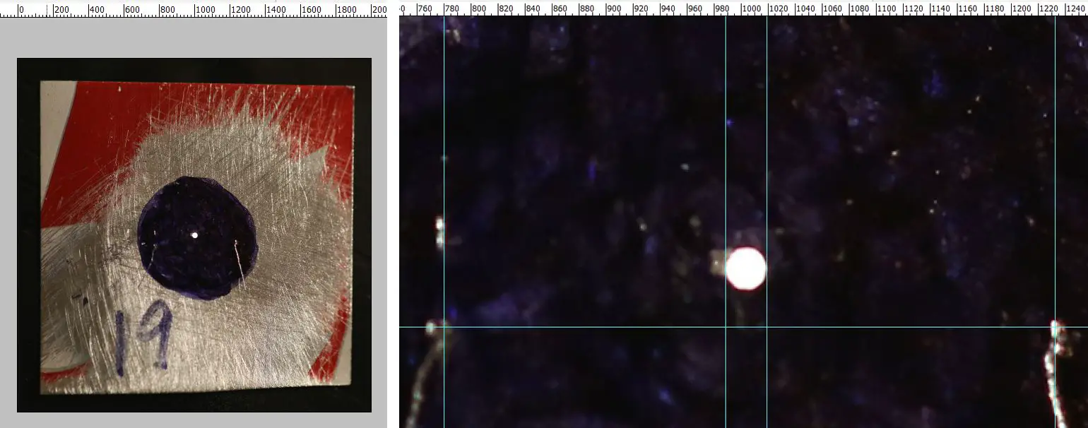
The pinhole diameter (in mm) is: 5 × (difference between the pinhole guidelines) ÷ (difference between the control mark guidelines). In my case, the pinhole diameter as measured by the Macro method is 5*(1019-988)/(1232-780) = 0.34mm.
For easy calculation, I also made an spreadsheet. You enter the four pixel values, and the program returns the pinhole diameter in millimetres. Feel free to use the spreadsheet, or download a copy for your own use.
Phone method
The Phone method is identical to the Macro method, except that you use a phone camera. It’s a bit less precise because phone cameras are not as good as a digital camera with macro lens (at least not yet!) but it will do the job.
Below left is a close-up photo with my Google Pixel 2, opened in Photoshop. Below right, I zoomed in and drew guidelines as described above.
The pinhole diameter, like with the Macro method, is: 5 × (difference between the pinhole guidelines) ÷ (difference between the control mark guidelines). In my case, the pinhole diameter as measured by the Phone method is 5*(616–598)/(734–486) = 0.36mm. As before, you can also use the spreadsheet to calculate.
Exposure method
I haven’t seen this method anywhere else; I came up with it independently, but I don’t know if I’m the first to do so. It sounds more complicated than the earlier ones, but once you get your head around it (and assuming you have a interchangeable-lens digital camera for which you can make a “pinhole body cap”), it’s fast and I believe more accurate. This is now my method of choice for pinhole measurement. Moreover, unlike the other methods, the Exposure method can give you the effective aperture for non-circular pinholes, e.g. slit pinholes (which people use for aesthetic reasons) or badly-made pinholes.
In short, the idea is to take a photo of a test target with a regular lens, with known ISO, shutter speed and aperture settings. Then take the same photo with the pinhole, keeping the ISO fixed and adjusting the shutter speed until you get a near-identical histogram. Since we know the lens aperture, the difference between the two shutter speeds allows us to calculate the pinhole aperture.
Equipment and test target
You need an interchangeable-lens digital camera with (a) manual controls and (b) instant review function with histogram. It should also have a lens, plus a spare body cap on which you can mount your pinhole. A tripod is convenient but not essential. And you need a computer, on which you display a test target like the one below (feel free to download this one, or make your own).

Mounting a pinhole on a digicam
For the pinhole conversion, I simply drilled a hole in the centre of my body cap and put lots of tape around it. Mounting a pinhole is very quick. I peel off a corner of the tape matrix, insert the pinhole so it’s centred in the body-cap hole, and tape back it down again. With this setup, you can also explore digital pinhole photography, which is a fun thing in its own right.
Pinhole “focal length”
So now you have a “pinhole lens”, but you also need to know its angle of view. For this, you need the “focal length”, which is the distance from the pinhole to the sensor. (“Focal length” is technically inaccurate in this context, because unlike a lens, a pinhole does not focus a real image – but let’s not be too pedantic.)
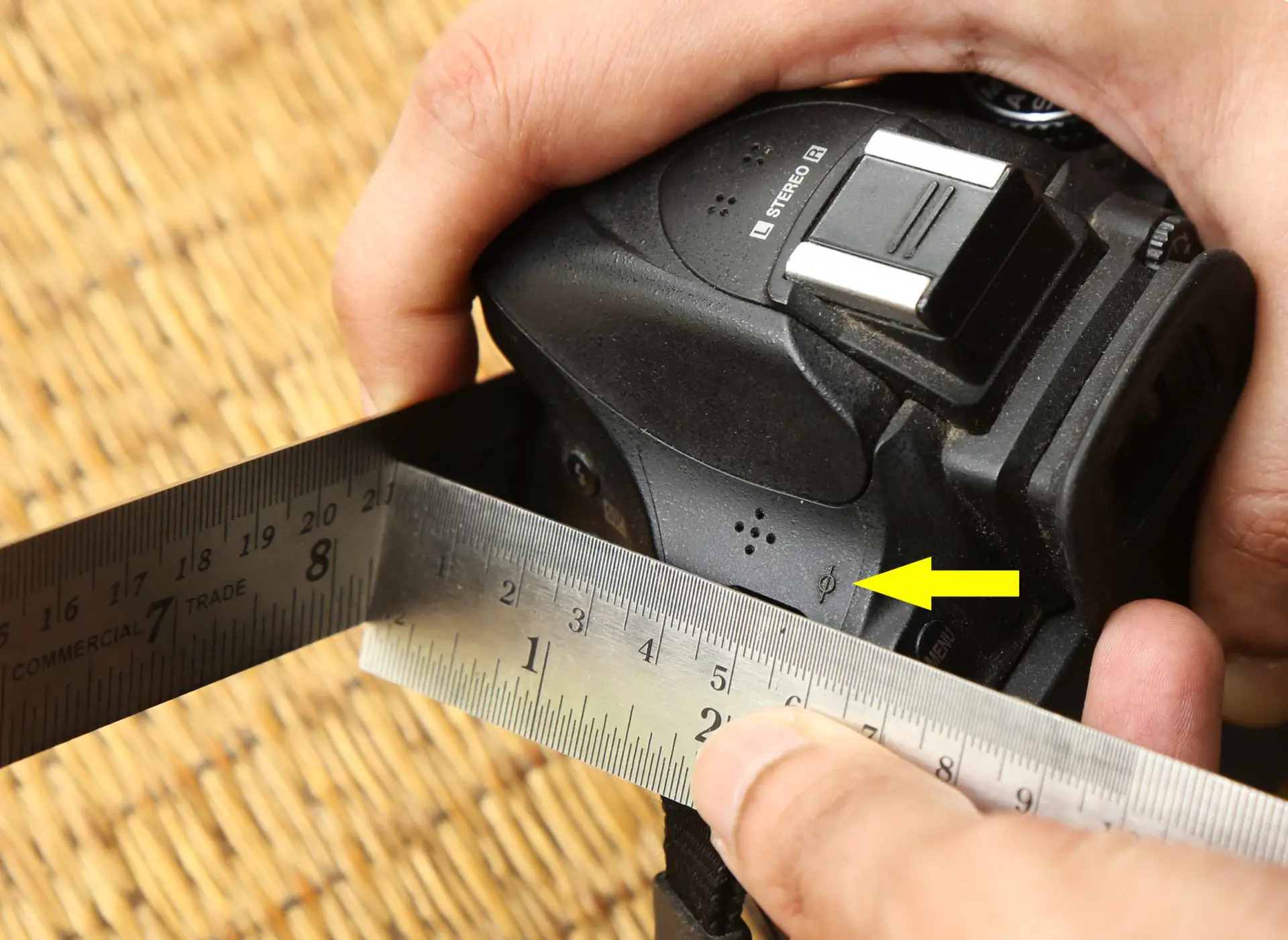
To find the focal length of the pinhole, simply measure the distance between the pinhole and the sensor plane, as shown below. Many cameras have a ⦵ symbol indicating where the sensor is located (I added a yellow arrow next to it). Perfect accuracy is not necessary; a 5mm error is not the end of the world.
If your camera doesn’t have an indication of where the sensor is, you can still estimate the focal distance as follows: look up your camera’s flange focal distance (usually given in the manual) and add the thickness of the body cap.
Knowing the pinhole focal length is helpful because a lens with the same focal length as the pinhole will also have the same angle of view. In practical terms, when the test target fills the frame with the lens, it will also fill the frame with a pinhole. A zoom lens is particularly helpful because you can replicate any pinhole focal length within the zoom range. On my DSLR (a Nikon D5200), the focal length of a pinhole mounted on the outside of the body cap is 53mm. I don’t have a zoom lens in this range, but I use my 50mm f/1.8 prime, which is close enough.
If you don’t have a lens with the same focal length, you can use the closest lens you have. You’ll be taking two photos – one with the lens and one with the pinhole, so just make sure that in each case, the test target fills the frame, moving the camera forward or back as needed. The framing just needs to be close enough, not exact.
Testing
Now for the actual testing. The photo below shows my test setup. The camera should be square to the test target (i.e. the sensor should be roughly parallel to the computer screen), but there is no need to go calibration-crazy. I try to keep the computer screen vertical, and the camera roughly level and at the same height as the centre of the screen, with the grey square centred in the viewfinder. The room should be relatively dark. Too much light shining on the screen can skew the results.
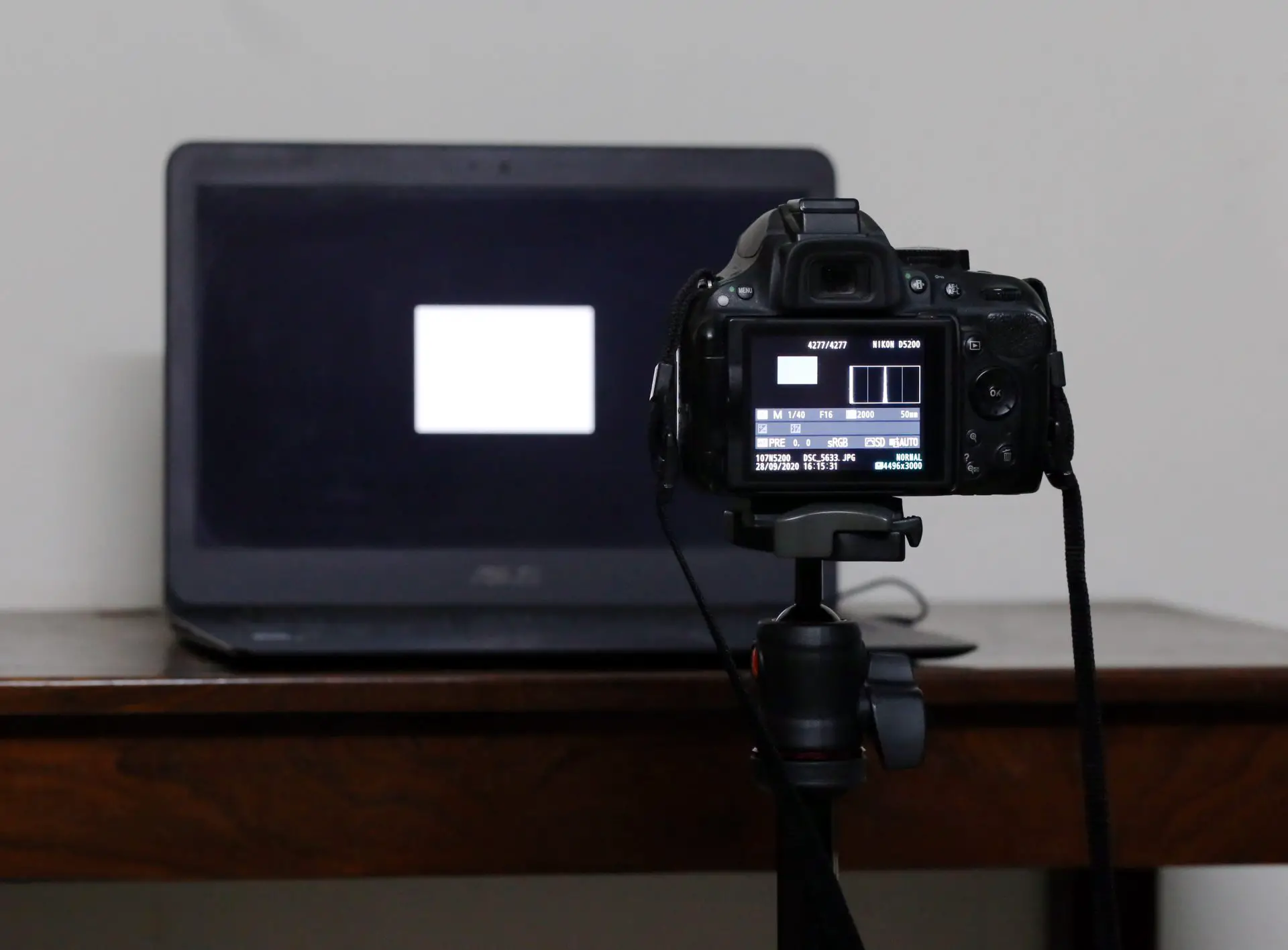
With a regular lens at f/16, take a photo of the test target. Try and keep the shutter speed at 1/30 sec or faster, otherwise the pinhole exposures will get inordinately long. If the image is too dark, increase the camera ISO or screen brightness – don’t change the aperture.
The histogram, as you can see from the photo above, shows two distinct spikes – one in the middle, representing the grey square, and one on the far left, representing the dark area around it. (My camera display helpfully shows vertical guidelines on the histogram. I try and tweak my exposure settings or monitor brightness until the middle spike is aligned with one of the guidelines, as shown in the photo. This makes the test easier, but it’s not essential.)
Next, swap out the lens for a pinhole, making sure the target still fills the frame. Increase the shutter speed (7 stops more is a good starting point) and take a photo. Adjust the shutter speed until you get the histogram spike in the same place as on the previous photo with the lens.
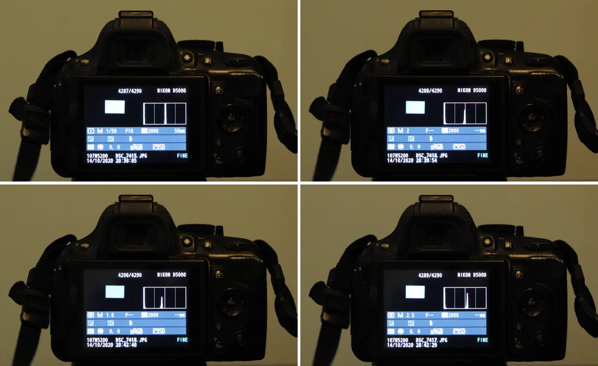
The test is surprisingly sensitive, down to ⅓ of a stop, which is the smallest exposure adjustment I can make on my camera. In the photos above, the histogram at top left (1/50 sec with lens) is nearly identical to the one at top right (2 sec with pinhole). If the pinhole shutter speed is ⅓ stop faster (1.6 sec, bottom left) or ⅓ stop slower (2.5 sec, bottom right), the spike looks clearly misaligned. So it’s easy to see when you get the right exposure with the pinhole.
The maths
Now comes the easy part. I made a spreadsheet where you enter three known values: (a) the shutter speed with lens at f/16, (b) the equivalent pinhole shutter speed and (c) the focal length. The program returns the pinhole diameter in millimetres. Feel free to use the spreadsheet, or download a copy for your own use.
Alternatively, copy-paste the following formula into the Google search bar:
c/(16*2^(0.5*log2((b)/(a))))
replacing a, b and c with the values given in the previous paragraph.
In my case, a=1/50 and b=2, as you can see from the photo above. My focal length, c, is 53 as I mentioned earlier. Using the formula, the pinhole diameter as measured by the Exposure method is 0.33mm.
Comparing the methods
When carefully employed, all these methods produce very similar measurements. To recap, I measured the same pinhole using four different methods, and the values I got were:
Scanner method: 0.35mm
Macro method: 0.34mm
Phone method: 0.36mm
Exposure method: 0.33mm
To confirm, I measured three more pinholes of different sizes using all four methods, and in each case, the deviations were insignificant. So if you ask me, all these methods will do the job; the “best method” ultimately comes down to equipment availability or personal preference.
The advantage with the Scanner method is being able to directly measure with the millimetre ruler in Photoshop, without the need to make control marks as you do for the Macro or Phone methods. It could also be useful if you have a scanner, but not a digital camera with macro lens, nor a good phone camera. But as I said, with my 600 dpi scanner, small or medium pinholes are hard to see.
The Exposure method is now my method of choice. It sounds complicated, but once you get your head around it (and assuming you have the equipment), it’s accurate and fast. Set up the display, take one shot with the lens at f/16, take another with the pinhole where you match the exposure, and enter the numbers into the spreadsheet. Moreoever, this method relies on the actual amount of light admitted by a pinhole, and not the physical dimensions which may be irregular. So it is also capable of measuring non-circular pinholes, where the other methods falter.
If the Exposure method is not for you, you may prefer the Macro method or Phone method. The phone method is a bit less precise due to lower resolution, but it will do the job.
There are some older methods, like magnifying a pinhole by putting it in the negative-holder of an enlarger, or in a slide mount in a projector. But unless you’re an analogue fanatic, I think magnifying with a scanner, digital camera or phone is more convenient.
The high-end option is a microscope with a stage micrometer and eyepiece reticle. I don’t have access to one, but in theory it should produce accurate and easy measurements, at least for circular pinholes.
Calculating pinhole aperture
To find the aperture, simply divide the focal length by the pinhole diameter. My spreadsheet has this function too, but it’s the simplest calculation of all.
For the pinhole I just measured, the diameter is 0.33mm (Exposure method). So the aperture on my digital camera is 53/0.33 = f/161 (I round aperture values to the nearest integer). On my analogue camera, which has a focal length of 60mm, the aperture is 60/0.33 = f/182.
Optimal pinhole size
Measuring the pinhole diameter is useful not just for calculating the aperture, but also if you care about “optimal” pinhole size.
What is optimal?
“Optimal” is an interesting word. In the pinhole context, people tend to assume it means “sharpest”, but I think it’s a lot more flexible than that. For example, Jeff McConnell does street photography(!) with a pinhole camera, and he told me he often uses bigger pinholes than those which would theoretically maximise sharpness. His priority is faster shutter speeds; for him, that is optimal.
Even “sharpness” is an imprecise term. Contrast and resolution both contribute to perceived sharpness, and with pinholes (as the next section shows), there is a trade-off between the two. But for now, I’ll use the term “optimal size” to mean the size which maximises perceived sharpness. Later on, I’ll get more precise.
The theory
The concern with pinhole sharpness is of ancient origin. Ibn al-Haytham (965–1040 AD) was an Arab mathematician, and a pioneer of optical science. He converted a room into a camera obscura, and in a treatise called On the Shape of the Eclipse, he noted that that a sharp image of the Sun only appears when the size of the aperture “amounts to one grain of barley”.
The optimal size, we now know, is a function of focal length (to recap, the focal length is is the distance from the pinhole to the surface on which the image is projected). The longer the focal length, the larger the pinhole should be. We also know that for a given focal length, smaller pinholes form sharper images… until they get too small, and diffraction makes the image unsharp again. Therefore the optimal pinhole lies somewhere in between.
But what exactly is the optimal size? There are several online calculators, but they often give different results. Let’s take my DSLR focal length of 53mm. Pinhole.cz says the optimal diameter is 0.32mm, while ****@****rs.com/pinsize.htm”>Guillermo Peñate’s calculator gives 0.27mm. Who is right? Other calculators produce still other values, and some don’t even reveal the formula they use. I decided to get to the bottom of this… and to make my own calculator, with a transparent formula, as well as the justification for choosing it.
Optimal resolution
In an 1891 paper published in Nature titled “Some Applications of Photography”, Lord Rayleigh calculated that the pinhole diameter for optimal resolution is 2√(fλ), where:
f is the focal length; and
λ is the wavelength of light (generally approximated as 0.00055mm, see below).
Confusingly, in another 1891 paper titled “On Pin-Hole Photography”, Lord Rayleigh gave a different formula: 1.9√(fλ). But this formula yields very similar values; the difference is not worth losing sleep over.
Wavelength of light
λ is generally taken to be 0.00055mm (550 nm), which is the wavelength of green light. With this formula, the optimal pinhole diameter for my DSLR focal length turns out to be 2*sqrt(53*0.00055) = 0.34mm.
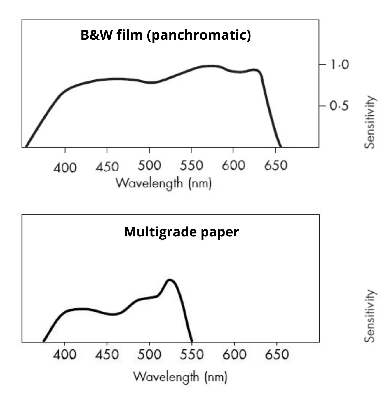
0.00055mm is a good approximation for most purposes, since green is in the middle of the visible spectrum. This is the value I use for tests with my digital camera. However, in my analogue camera I use photographic paper. Paper has little or no sensitivity to longer wavelengths (yellow and red) and high sensitivity to shorter wavelengths (blue and even ultraviolet). So for paper I use λ = 0.00048mm (480nm). Here are typical spectral response curves for panchromatic film and B&W paper, which hopefully show why 550 nm is a good approximation for most purposes, but 480nm is better for paper.
Optimal contrast
2√(fλ) is a nice and easy formula, but it’s not the whole story. In a 2004 paper titled “The Pinhole Camera Revisited, or The Revenge of the Simple-Minded Engineer”, Kjell Carlsson (Professor Emeritus of Imaging Science and Photography at KTH Royal Institute of Technology, Stockholm) notes that it’s not all about resolution; perceived sharpness also depends on contrast. To most observers, an image with high resolution and low contrast appears less sharp than an image with slightly lower resolution and higher contrast. In theory, subjectively sharper images can be produced by using a slightly different formula for pinhole diameter, optimising for contrast rather than resolution. This formula is 1.56√(fλ). Note that only the constant has changed: 1.56 instead of 2. The √(fλ) part remains the same.
Using the new formula, the optimal pinhole diameter for my DSLR focal length turns out to be 1.56*sqrt(53*0.00055) = 0.27mm, clearly smaller than the Rayleigh formula.
The trade-off between sharpness and contrast is nicely illustrated by a graphic from the paper, which Prof Carlsson kindly allowed me to reproduce here:
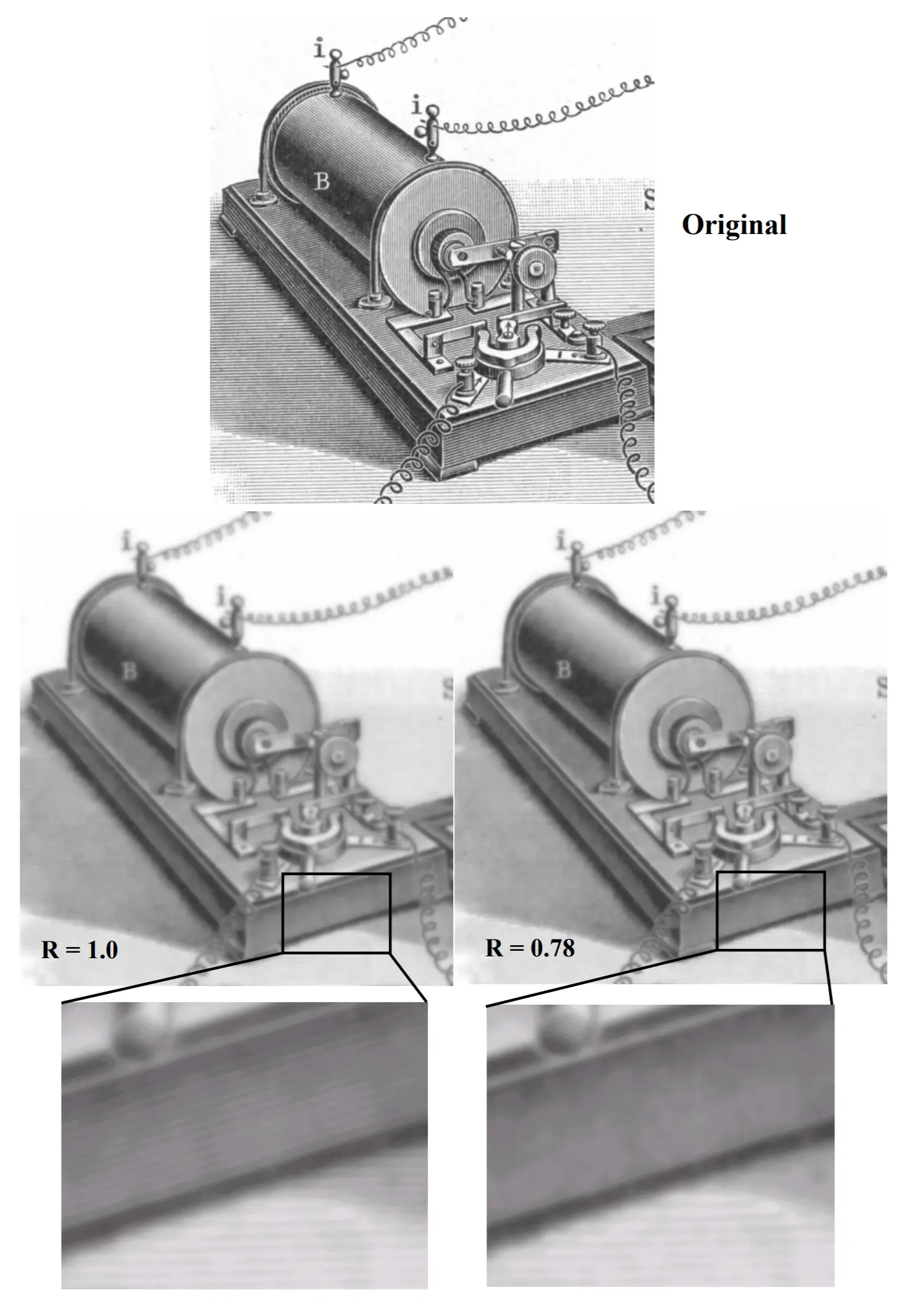
The graphic shows the original image (top), and simulated pinhole images using the Rayleigh formula 2√(fλ) (left) and 1.56√(fλ) (right). (R=1.0 and R=0.78 relate to pinhole radius. For diameter, the constants are doubled: 2 and 1.56 respectively, which correspond to the formulae which I gave earlier.) The image on the left has higher resolution – the magnified version shows the slanting pattern which the other does not. But looking at the unmagnified images, the one on the right looks subjectively shaper.
In short, you can optimise either for resolution using 2√(fλ), or for contrast using 1.56√(fλ); you can’t have your cake and eat it. As the economist Thomas Sowell once said, “There are no solutions, only trade-offs.”
Object distance
There is one final factor to consider. The formulae given above are slightly simplified, in that they relate to objects at infinity. The general formulae for optimal pinhole diameter, applicable to any object distance, are as follows:
2√(fλ/(m+1)) for resolution, and
1.56√(fλ/(m+1)) for contrast.
As before, f is the focal length, and λ is the wavelength of light. The new variable, m, is magnification. m = f/d, where d is the distance from the object to the pinhole.
For objects at infinity, d is much greater than f, so m is taken to be 0, and the general formulae reduce to the simplified formulae given earlier. If the object distance is equal to the focal length, m equals 1 (macro), and if an object is even closer, m is greater than 1. Positive values of m produce smaller a optimal pinhole diameter, and I found that this does in fact make a visible difference in sharpness (I plan to write a future post about macro photography with pinholes, where I’ll share the results). But for object distances which are more than three times the focal length, m can safely be ignored; the simplified formulae given earlier are a perfectly good approximation.
Testing for sharpness
So much for the theory. The real world is potentially more messy, especially if you’re using homemade pinholes as I do. To be clear, I have no doubts about the correctness of the formulae, which have been devised by people far smarter than me. But the theory assumes perfect pinholes, and homemade ones are not perfect. This made me wonder: would my homemade pinholes match the theoretical predictions? Or would other variables and imperfections play a bigger role?
I also wanted to know what pinhole formula to use in practice. Would I be able to see the difference between optimal resolution and optimal contrast? Would it matter if I chose entirely different values? There was only one way to find out: more testing!
To that end, I made pinholes in a variety of sizes, and then subjected them to three types of tests:
(a) digital tests with a US Air Force optical test chart
(b) digital tests with a “real world subject”
(c) analogue tests with a “real world subject”.
Digital vs analogue testing
Before describing the tests, a quick word about my digital and analogue testing processes. My digital tests were carried out on a crop-sensor DSLR (Nikon D5200), and my analogue tests were on a homemade pinhole camera using 6×4″ photographic paper. I don’t want to get into the whole digital vs analogue debate, but it’s worth noting that my digital tests are both less flattering and more flattering than my analogue tests.
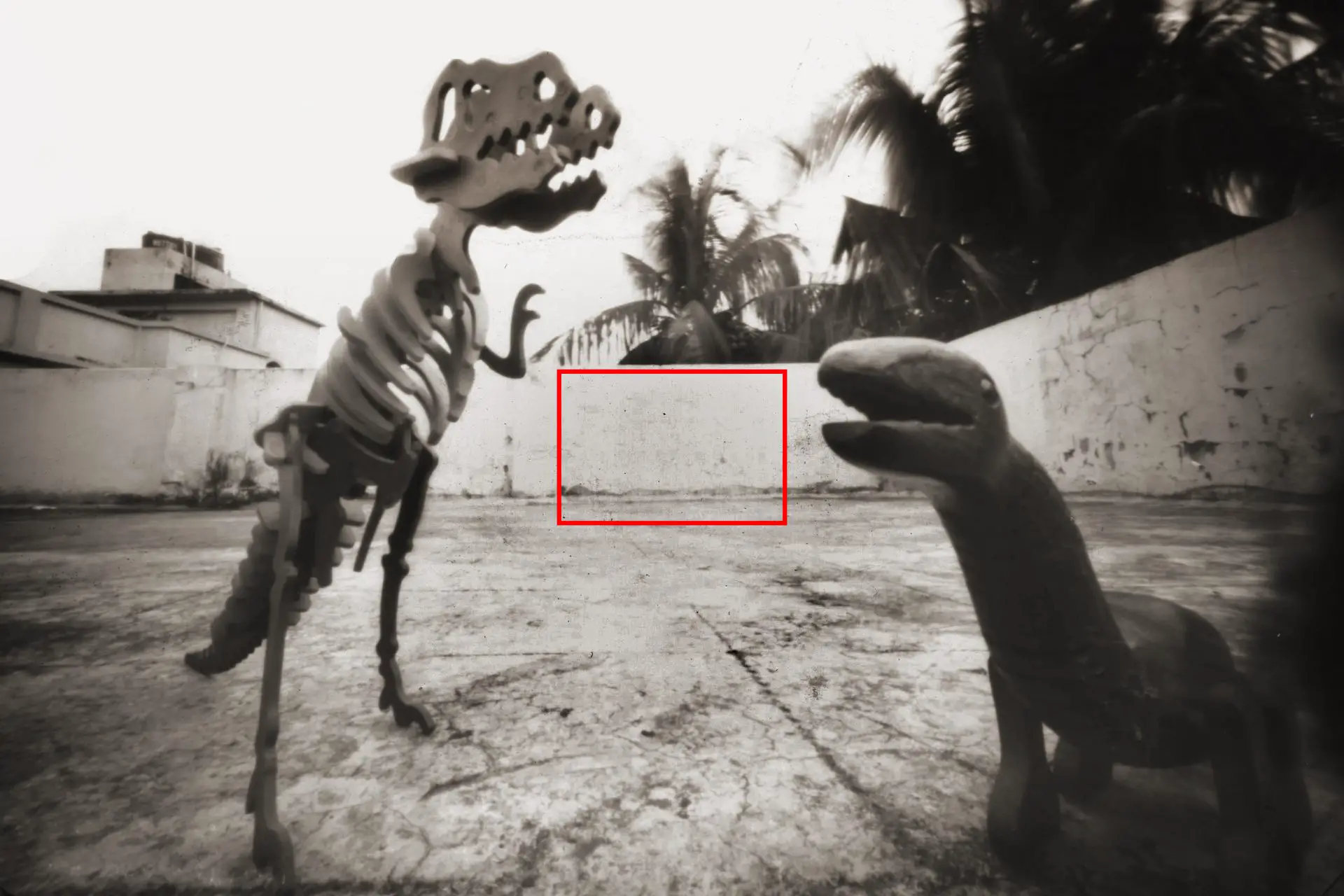
They are less flattering than analogue because the APSC sensor size is far smaller than the image circle formed by the pinhole at that distance. How big is the image circle exactly? That depends on how much vignetting you’re willing to tolerate. Pinhole images suffer from vignetting approximated by the cosine-fourth law (this excellent paper by Matt Young goes into more detail). For me, vignetting of 2 stops in the corners is easily acceptable in pinhole photography. On that premise, at 53mm (my DSLR focal length), the pinhole forms an image circle with a diameter of 106mm. My DSLR sensor diagonal is only 28.2mm. So we’re “throwing away” a lot of resolution – like using a crop sensor on a large-format camera.
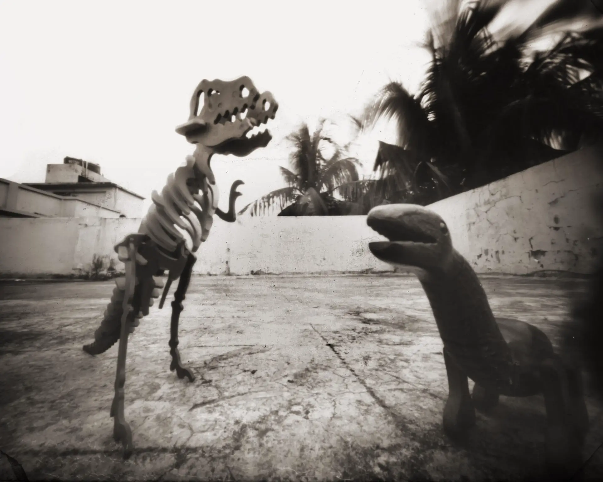
Remember the dinosaur photo at the top of this post? That was taken with my analogue camera on 6×4″ photo paper. Had I used an APSC sensor on the same plane as the paper, it would only image the area inside the red rectangle below.
My digital tests are more flattering because, thanks to the small sensor, we are only looking at “centre-sharpness”. Pinhole images not only vignette, they are also less sharp in the corners. Close to the axis, the pinhole looks round. As you move further away, it’s effectively elliptical, as shown in the diagrams below. And as we know, any pinhole shape other than round is suboptimal.

Currently, I am more interested in analogue pinhole photography. So ideally, given what I just said about digital–analogue discrepancies, I ought to have done all my tests with my analogue camera. But paper is slow (around ISO 5), expensive and needs to be developed. With digital, I get high ISO, no marginal cost and instant results, all of which make it ideal for testing. If we keep the aforementioned discrepancies in mind, I believe we can still draw meaningful conclusions.
Digital USAF test
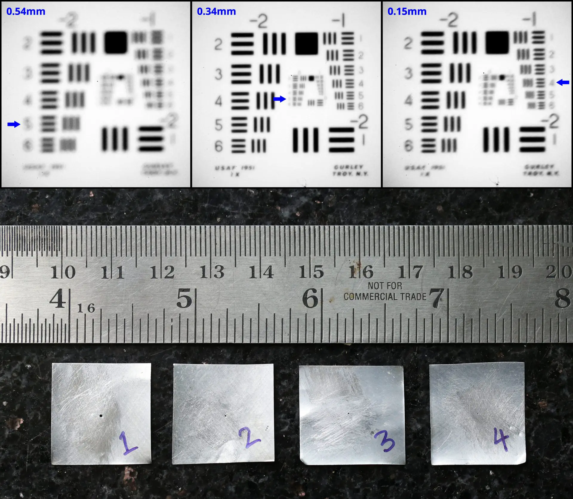
For this test, I used a US Air Force test chart. There are several versions of the chart, but the one I used looks like this:
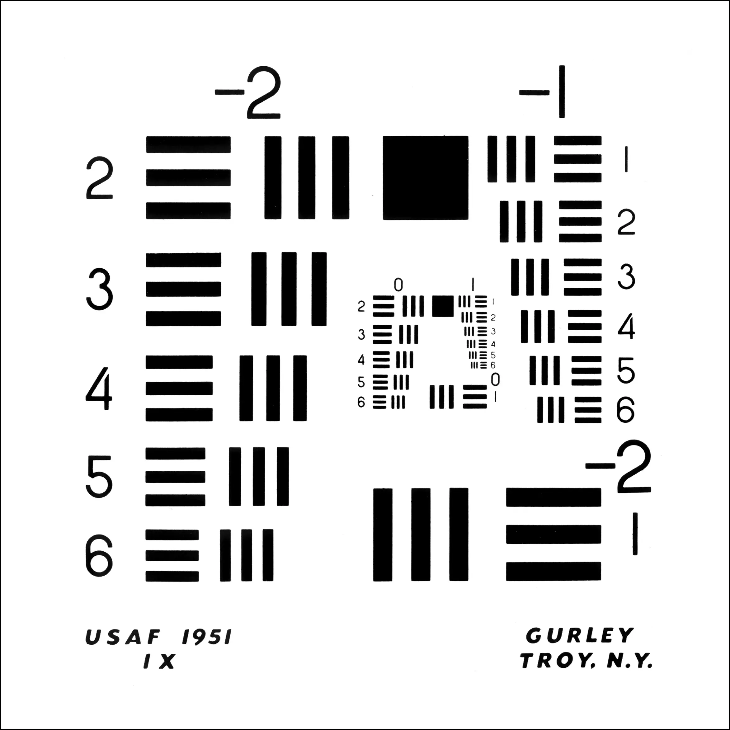
The chart has 4 groups of test patterns. The largest, Group –2, starts at bottom right and continues at top left. The next, Group –1, starts at top right. The inner layer has Group 0 (starting at bottom right and continuing at top left) and Group 1 (the smallest, top right). Each group has 6 elements, numbered 1 to 6 in decreasing order of size. Each element has 3 horizontal and 3 vertical bars. The idea is to find the smallest element whose bars can be resolved by a lens – or in this case, a pinhole.
I made pinholes of various sizes, measured by the exposure method described above, and tested them using the setup described below.
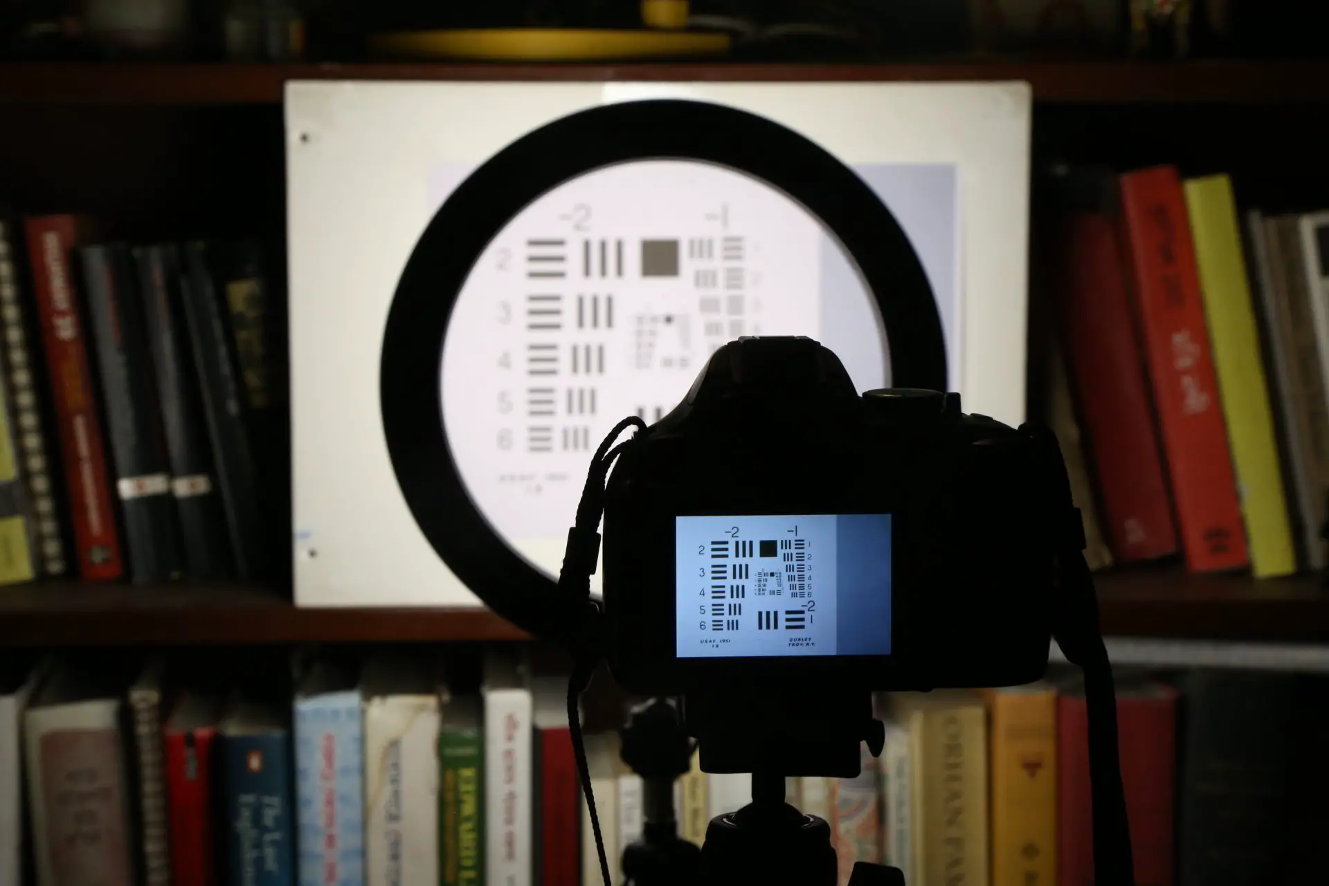
I printed the test chart on A4 paper, and mounted it on mat-board. (The print size is not important because we’re not measuring the MTF, just comparing different pinhole sizes.) I illuminated it with a ring LED (the circular thing in the photo above), and set up my Nikon D5200 on a tripod at a distance of 80cm, which is where the test pattern fills the frame. I also made sure that the camera is square to the test target (this Lensrentals post has more detail on how to do that).
I then mounted my pinholes one by one on the DSLR, and photographed the test target. Since the pinholes are of different sizes, I adjusted the shutter speed to make sure the exposures are identical. The easiest way to do this is to check the histogram on the LCD.
The images below show the test chart, photographed with 7 different pinholes in increasing order of size. For comparison, I also added a photo taken with a Nikkor 50mm f/1.8 lens at the same distance. I cropped the pinhole images identically, and applied identical contrast adjustments in Photoshop (same values for black and white input levels). Finally, for reference, I added (a) the pinhole diameter and (b) an arrow showing the smallest element where I can resolve both horizontal and vertical bars. (Your evaluation of the smallest resolved element may be different because I was looking at high resolution images, while on the website you’re seeing compressed JPEGs. In any case, this is somewhat subjective. But again, we’re not measuring the MTF, merely comparing. So we just need to be consistent.)
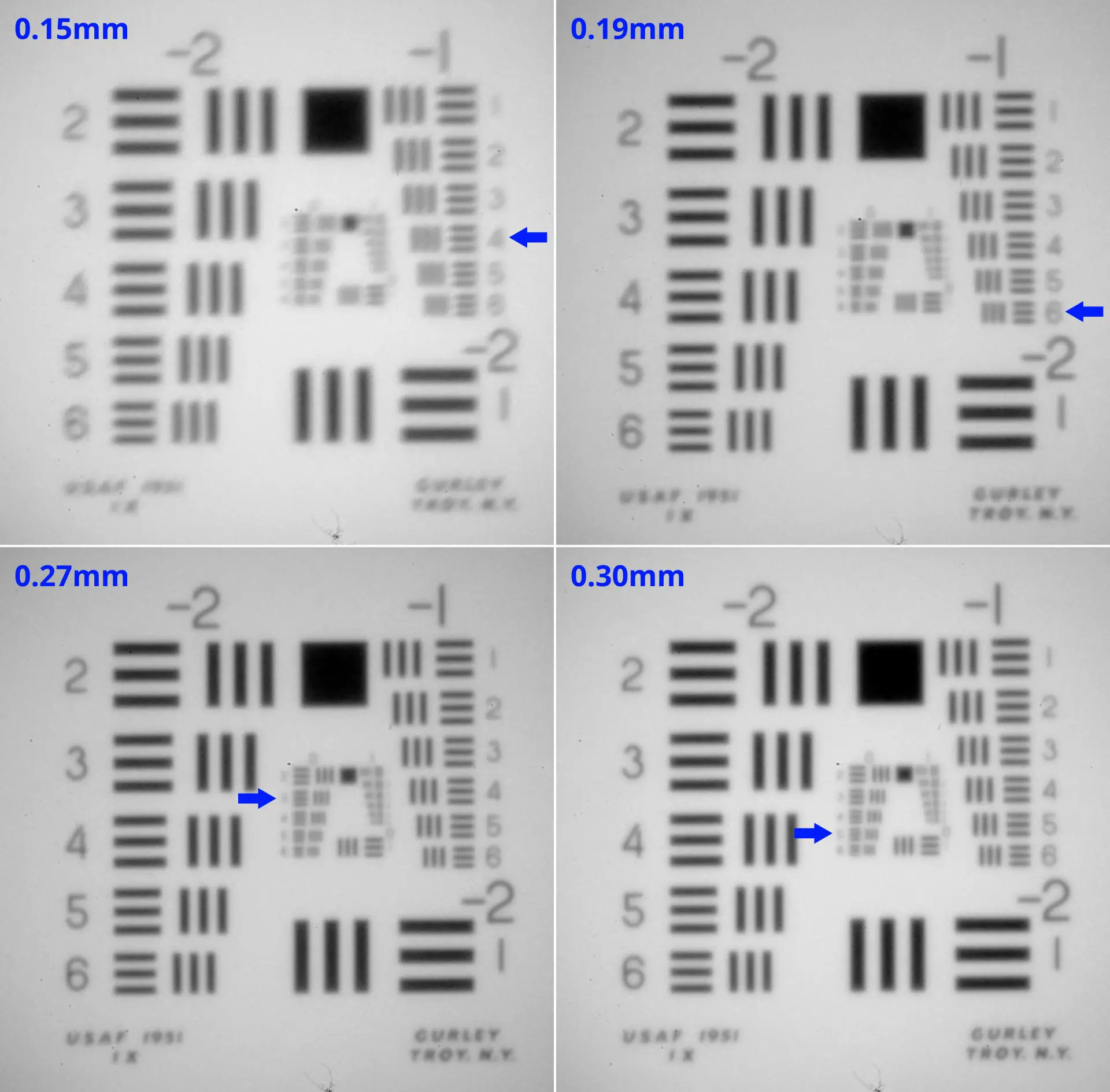
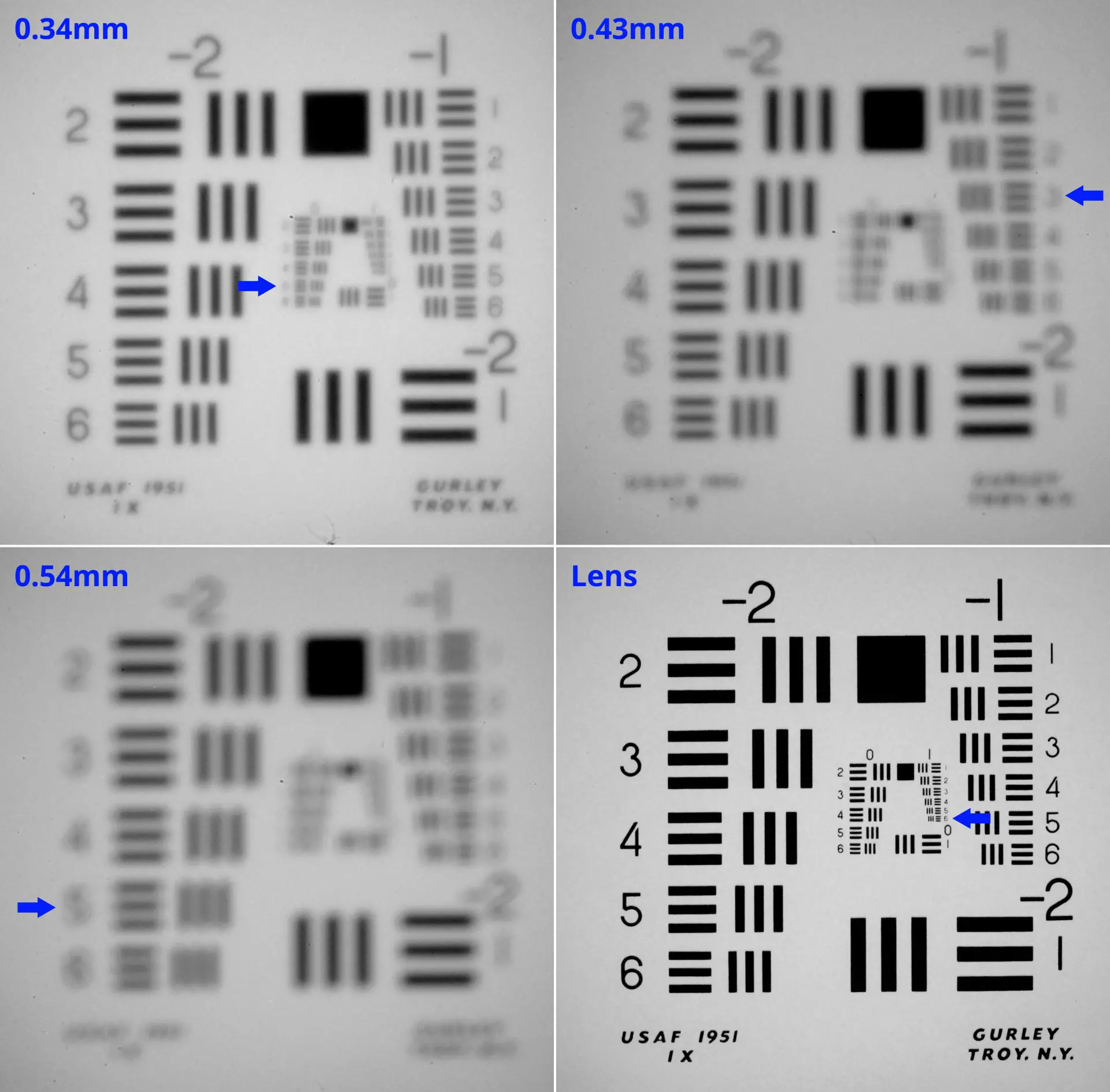
What do we see from the charts? Starting with the 0.15mm pinhole, resolution gradually improves, peaking with the 0.30mm and 0.34mm pinholes. After that, it deteriorates dramatically: 0.43mm is even worse than 0.15mm. Unsurprisingly, the lens (bottom right) blows them all out of the water.
Does this match the theory? In general, yes. We can clearly see that large pinholes produce unsharp images. Smaller pinholes are sharper, until diffraction sets in. Beyond that point, smaller pinholes get progressively less sharp. I won’t go into the physics of why this is so, but if you’re interested, Matt Young’s paper has more details. He also explains the interesting phenomenon of “spurious resolution”, where three very unsharp bars look like two relatively sharp bars. You can see this in the 0.54mm image, in the vertical bars at top right.
Now let’s look at the formulae. Recall that theoretically, the optimal diameter is:
2√(fλ/(m+1)) for resolution, and
1.56√(fλ/(m+1)) for contrast.
In my case, the variables are as follows:
f (focal length) = 53mm
λ (wavelength of light) = 0.00055mm
m (magnification) = f/d = 53/800 (the target was 80cm from the pinhole).
With these values, the theoretically optimal diameter is 0.33mm for resolution and 0.26mm for contrast.
Looking at the images, the sharpest pinholes are 0.30mm and 0.34mm. Both resolve Group 0, element 5. If I look really closely, 0.34mm is the sharper of the two (only just). This matches the theoretical prediction of 0.33mm for optimal resolution – a nice result. The 0.27mm pinhole ranks third, resolving Group 0, element 3. Theoretically, 0.27mm should have better contrast, but it’s not apparent to me from the photos.
To evaluate contrast – and also because in real life we don’t take photos of test charts! – I next did some tests with a “real world” subject.
Digital “real world” test
For this test, I eliminated the smallest and largest pinholes, since they are clearly inferior, and tested the remaining five. (It’s worth noting that those pinholes are not inferior per se, just not optimal for the DSLR focal length.)
As before, I setup my Nikon D5200 on a tripod. I mounted my pinholes one by one, and photographed some buildings in my neighbourhood. Since the pinholes are of different sizes, I adjusted the shutter speed to make sure the exposures are identical. The easiest way to do this is to check the histogram on the LCD.
The images below were photographed with 5 different pinholes in increasing order of size. For comparison, I also added a photo taken with a Nikkor 50mm f/1.8 lens at the same distance. I did not crop, adjust contrast or otherwise edit the images, just added the pinhole diameter for reference.
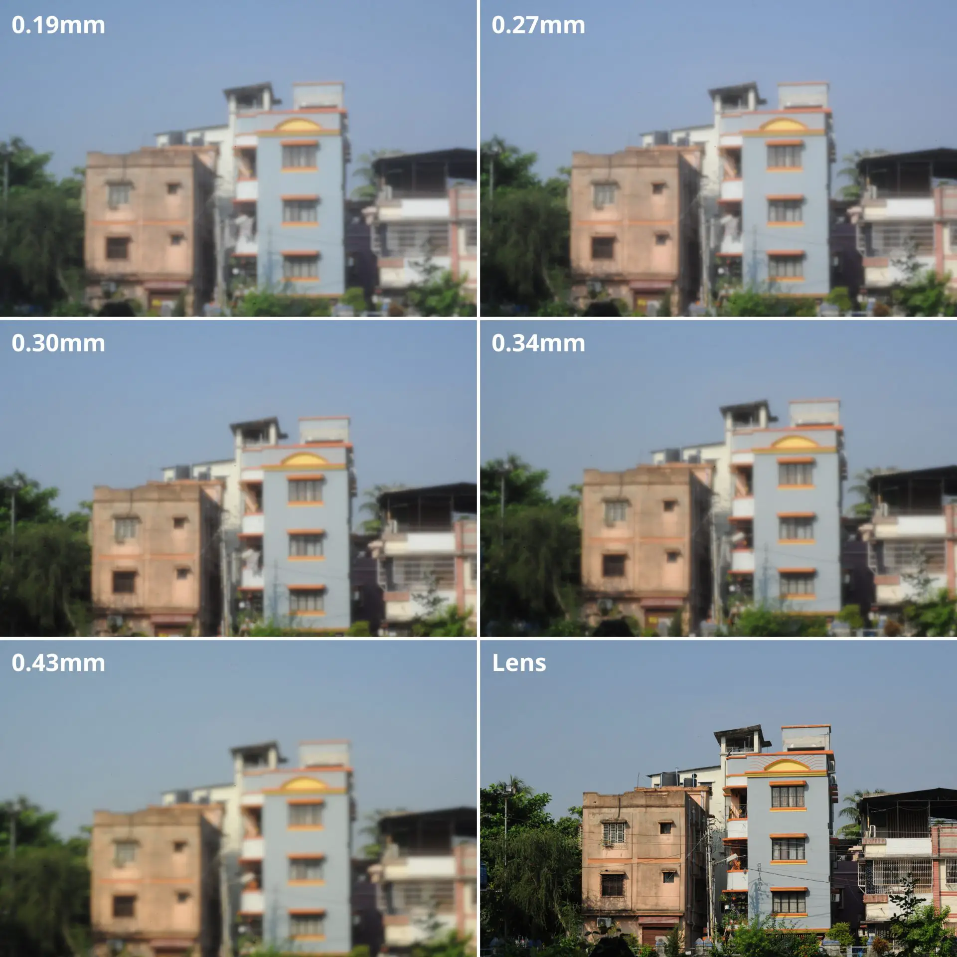
Here, the object is near infinity (m = 0), so the optimal diameters are slightly different to those in the USAF test where the object was only 80cm away. For these tests, the theoretically optimal diameters are 0.34mm for resolution and 0.27mm for contrast (as opposed to 0.33mm and 0.26mm for the USAF test – a negligible difference).
Once again, 0.34mm and 0.30mm look the sharpest (at least they do in the high resolution images; it may not be apparent on your screen). 0.27mm is close behind, followed by 0.19mm and 0.43mm. The order matches the USAF tests. Theoretically, the 0.27mm pinhole (optimised for contrast) should be subjectively sharper, but in my tests, the 0.34mm pinhole (optimised for resolution) seems to come out on top. I will come back to this apparent discrepancy shortly, after I describe my analogue test.
Analogue “real world” test
Finally, I did a real-world test with my analogue camera, using 6×4″ photo paper. The camera has a focal length f = 60mm (slightly longer than my DSLR). The subject was 15cm away, so m = 60/150. Because photo paper has a different spectral response as explained earlier, I use λ = 0.00048mm (as opposed to 0.00055 for the digital tests).
With these values, the theoretically optimal diameter is 0.29mm for resolution and 0.22mm for contrast.
Shown below are analogue photos with a 0.27mm pinhole (in the optimal range) and a 0.34mm pinhole (the top performer in the previous tests, but in this case slightly larger than optimal). The subject is one of the toy dinosaurs featured at the top of this post. The exposure times were 4 mins and 2:20 mins respectively. I scanned and inverted the paper negatives, applying identical (very minor) contrast and brightness adjustments.
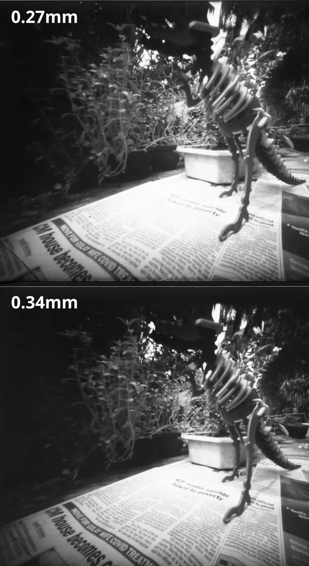
As photos, they’re nothing special – there’s too much clutter, and I got the framing wrong and cut off part of the dinosaur’s head – but they’re good enough for test purposes. The first one is slightly over-exposed, but in terms of sharpness, I can’t see a meaningful difference between the two images.
Resolution vs contrast revisited
To recap: for any given focal length, there is not one but two optimal pinholes – one for resolution (larger) and one for contrast (smaller). Theoretically, the latter should produce images which are subjectively sharper, but in my tests so far with both digital and analogue photos, I can’t see a meaningful difference. If anything, the former – using the Rayleigh formula: 2√(fλ/(m+1)) – seem slightly sharper.
To double-check, I made two 0.34mm pinholes (optimal resolution) and two 0.27mm pinholes (optimal contrast), and took digital photos of the USAF chart as well as real world subjects with all four pinholes. The purpose was to control for inconsistencies in my pinhole making process. In each case, the 0.34mm pinholes produced sharper images. This apparently goes against the theory that optimal contrast pinholes produce images which look subjectively sharper.
I showed my results to Prof Carlsson, whose paper on optimal contrast I cited above. His email, part of which I quote below, puts the results in perspective:
Concerning the tradeoff between contrast and resolution, the difference in image result is rather subtle between the two cases even theoretically. What happens in the imaging process (electronics/computer or wet chemistry) can actually affect the results a lot. You may be interested to know that in the book “Way Beyond Monochrome” by Lambrecht & Woodhouse (Focal Press, 2nd ed.), experiments similar to yours are reported. They find that the smaller aperture, thanks to higher contrast, tends to produce images that look sharper. But again, the difference is subtle.
After I published this post, Tim Parkin left a comment linking to an article in On Landscape magazine, where he did some similar tests (I have edited my post to take his results into consideration). All my tests were with homemade pinholes, but Tim’s tests are great because he also compared his homemade pinholes to precision pinholes made for laboratory use. The lab pinholes are very accurately made using high-intensity particle beams(!) and with an extremely thin support material which is tapered to almost nothing near the pinhole edge.
The lab pinholes seem to match the theory – optimal-resolution pinholes resolve finer detail but optimal-contrast pinholes deliver sharper results. This is clear from his 65mm landscape scene where 0.3mm and 0.4mm are optimised for contrast and resolution respectively (the images from the lab pinholes are marked with an asterisk).
Personal conclusions
Based on my tests, supplemented by Prof Carlsson’s remarks and Tim Parkin’s tests with lab pinholes, my conclusions are as follows. With high-precision pinholes, the optimal contrast formula – i.e. diameter = 1.56√(fλ/(m+1)) – produces sharper results, just as the theory predicts. However, with my homemade pinholes, perhaps due to minuscule irregularities at the pinhole edge, images from optimal-contrast pinholes are not as sharp as they should be. Instead, the optimal resolution formula – i.e. diameter = 2√(fλ/(m+1)) – comes out on top. Your mileage may vary, so if you want to be totally sure, the best way is to do your own tests.
Since I currently use homemade pinholes, if I want sharp images I favour the optimal-resolution formula. It also has the advantage of producing a slightly larger diameter, which translates to shorter exposure times.
Straying from these formulae in either direction (bigger or smaller) does produce a noticeable reduction in sharpness. But depending on your photographic goals, straying might also be “optimal” – for example, if you are prepared to compromise on sharpness because you want shorter exposure times, or if you simply want a blurrier image for aesthetic reasons.
Optimal size calculator
There are many optimal pinhole size calculators online, but I made a spreadsheet tool which suits my needs. If you find it helpful, feel free to use it, or download a copy for your own use.
My spreadsheet has a simple calculator and a complex calculator (an idea I borrowed from Chris Patton). In each case, you can either enter your focal length to get the optimal pinhole diameter, or enter your pinhole diameter to get the optimal focal length.
The simple calculator is… simple. The complex calculator lets you enter additional variables: wavelength of light and magnification. It returns two results, one based on optimal resolution and one on optimal contrast. As I said, my current preference is for the former, but I will continue to experiment further.
Conclusion
Well I did say this was going to be long and technical…
If you’re into the technical stuff like I am, hopefully you’ll find at least some parts of this post useful, or – who knows! –maybe even interesting. I’m also learning as I go, so let me know if you have any additional tips for making, measuring or testing pinholes. And if you’ve done your own tests (I know I’m not the only one!) I’d be interested to hear your conclusions.
If you’re not into it… well, as I tried to show in my previous post, perfectly good pinhole cameras can be made with simple trial-and-error; in fact, some would say that’s more in keeping with the spirit of pinhole photography. Have fun, and see you in a couple of weeks’ time for a less technical (and hopefully more interesting) next instalment of this series.
Share this post:


Comments
Martin on Making, Measuring and Testing the “Optimal” Pinhole: Pinhole Adventures Part 3 – by Sroyon
Comment posted: 26/10/2020
Comment posted: 26/10/2020
Tim Parkin on Making, Measuring and Testing the “Optimal” Pinhole: Pinhole Adventures Part 3 – by Sroyon
Comment posted: 26/10/2020
Comment posted: 26/10/2020
Comment posted: 26/10/2020
Comment posted: 26/10/2020
davesurrey on Making, Measuring and Testing the “Optimal” Pinhole: Pinhole Adventures Part 3 – by Sroyon
Comment posted: 26/10/2020
What a wonderful article. Thank you for sharing it with us.
I’ve been interested in pinhole photography for about a decade, on and off, and have amassed a load of articles on both the practice and theory and yours stands out as one of the best.
I'm looking forward to reading your follow up to see how your experiments progress.
Dave
Comment posted: 26/10/2020
Kurt Ingham on Making, Measuring and Testing the “Optimal” Pinhole: Pinhole Adventures Part 3 – by Sroyon
Comment posted: 26/10/2020
Kurt Ingham on Making, Measuring and Testing the “Optimal” Pinhole: Pinhole Adventures Part 3 – by Sroyon
Comment posted: 26/10/2020
Comment posted: 26/10/2020
Ben Garcia on Making, Measuring and Testing the “Optimal” Pinhole: Pinhole Adventures Part 3 – by Sroyon
Comment posted: 26/10/2020
Looking at your math, I'll have to go back through my images as I don't think my math was right. Like you alluded to, there's so many different pinhole calculators with different formulations!
https://www.flickr.com/photos/saladgreens/albums/72157716630357762/with/24900236896/
Cheers and well done!
Comment posted: 26/10/2020
eric on Making, Measuring and Testing the “Optimal” Pinhole: Pinhole Adventures Part 3 – by Sroyon
Comment posted: 27/10/2020
I do not say that I understand everything ;-), but I like the work which is academic !
If you want to do a PhD on pinhole, you are very near.
And the introduction with Jurassic Park is wonderful, this is one of my favorite movie, and this one is probably the greatest.
Thanks and bravo for your passion.
I really feel more and more that I must try to work on pinhole, it is fun.
Comment posted: 27/10/2020
Frank on Making, Measuring and Testing the “Optimal” Pinhole: Pinhole Adventures Part 3 – by Sroyon
Comment posted: 18/03/2021
Comment posted: 18/03/2021
Frank on Making, Measuring and Testing the “Optimal” Pinhole: Pinhole Adventures Part 3 – by Sroyon
Comment posted: 18/03/2021
The various calculator recommendations range from .592 all the way up to .75 (with a range in-between). with .675 or .68 being the average. So... based on my need to achieve more 'clarity' (also open to interpretation like 'optimal') shall I go for a 0.6
Comment posted: 18/03/2021
Comment posted: 18/03/2021
Comment posted: 18/03/2021
Andrew on Making, Measuring and Testing the “Optimal” Pinhole: Pinhole Adventures Part 3 – by Sroyon
Comment posted: 17/05/2021
Comment posted: 17/05/2021
Amy Crook on Making, Measuring and Testing the “Optimal” Pinhole: Pinhole Adventures Part 3 – by Sroyon
Comment posted: 16/08/2021
Comment posted: 16/08/2021
Jim Goodin on Making, Measuring and Testing the “Optimal” Pinhole: Pinhole Adventures Part 3 – by Sroyon
Comment posted: 10/05/2023
Comment posted: 10/05/2023
John Creedy on Making, Measuring and Testing the “Optimal” Pinhole: Pinhole Adventures Part 3 – by Sroyon
Comment posted: 10/10/2023
I am just starting out on my own pinhole adventure. I was wondering how many people have worked on digital pinhole and simply took my old Nikon and played around with kitchen foil and other materials. I discovered for myself the need for small holes and clean holes. My past experience as scientist involved with optics helped and started to reveal comments and assumptions which remained unchallenged. The need for a perfect circle and the idea of optimal size really needed closer scrutiny. I am not convinced by diffraction limitations posing a lower size limit.
All current pinholes are subject to apparent diffraction but investigation reveals various possible areas of misunderstanding of the cause. Much emphasis is placed on descriptive equations and assumptions as to their validity. Over time the understanding changes and updated equations emerge. At the end of the day when an equation does not fit the evidence then the evidence wins out. So let’s focus on the evidence and rely less on equations.
Molecular scale interactions with light and interference from out of phase reflective light are almost certainly involved to create what is described as diffraction and the main cause is the thickness of the pinhole material itself. Then there is the light reflecting qualities of that material and any other surface treatment.
I am interested in opening up a discussion on these issues and exploring better materials for pinholes. I believe that much smaller pinholes can be made with alternative materials and methods.
I think that an ideal pinhole may involve a microscopically thin adsorbing coating with far lower contributions towards resultant diffraction. We shall see.
Meanwhile I would value comments on this subject. Perhaps others have already worked on this and I have yet to find their reports.
Comment posted: 10/10/2023