

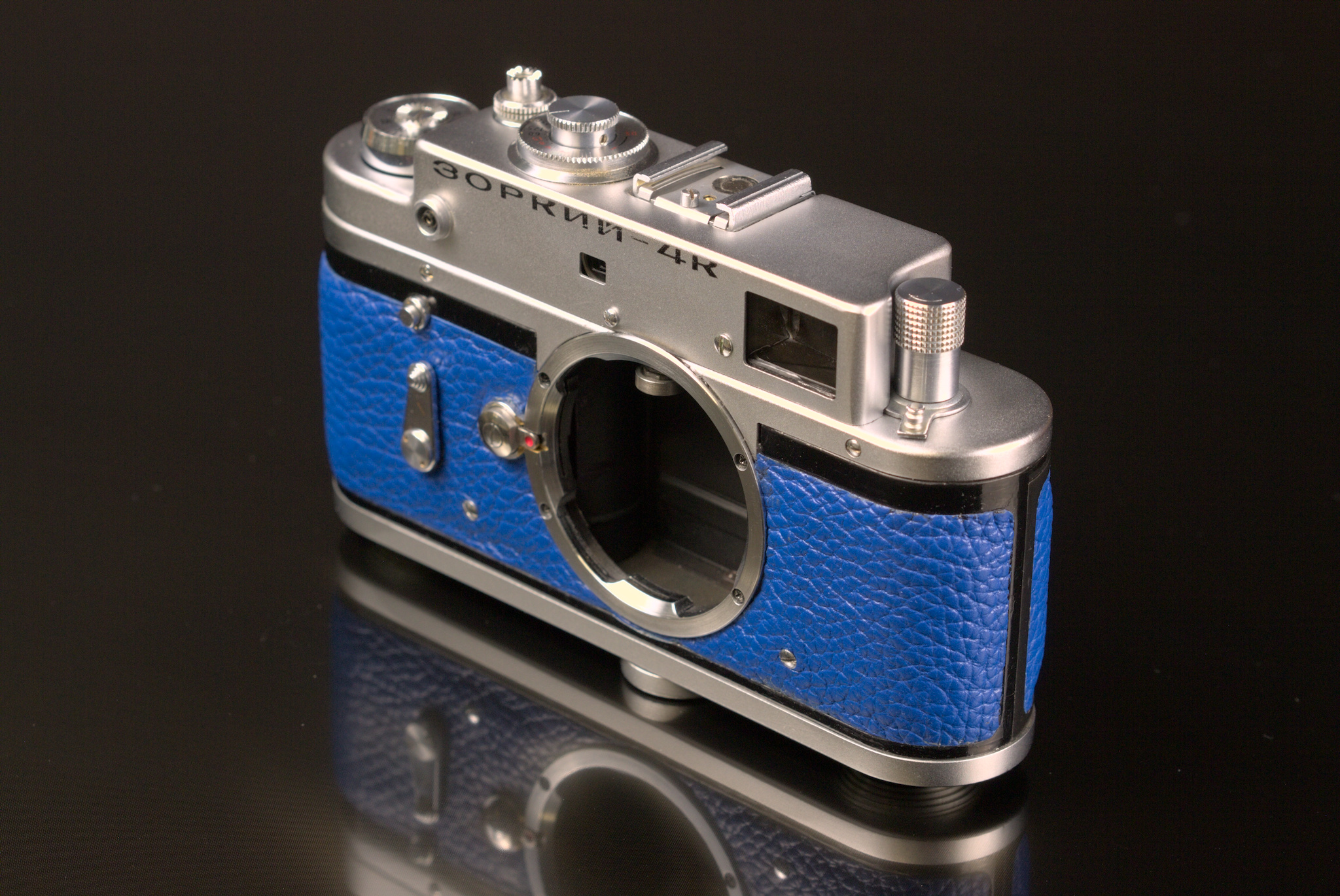
This is another unnecessary project of mine that had 2 goals: 1) to learn advanced repairs that I haven’t done before and 2) to satisfy my curiosity if an LTM mount camera can be converted to M mount. Number one seems reasonable in my mind but I have no idea why I had to scratch my itch on number two.My dad used to tell me the difference between simplicity and complexity is understanding. This has turned out to be so true with the camera repairs I started as a hobby years ago. More than just patience, I’ve learned if I really want to save a camera I need to be willing to kill a few in the process. Misunderstanding how a system comes apart is often only obvious to me after I get a chance to look at it all in parts and play with reassembly. And this in turn has created fears in my mind when I see interesting cameras that I want to try and save.
For one, I’ve been avoiding old cameras that have or are likely to develop shutter problems. As a fear conquering endeavor, I bought a for-parts Zorki 4K that I reasoned nobody would miss if I killed it learning how to replace a shutter. But selecting the Zorki was more than just finding a cheap camera. It was part of a long process of systematically identifying LTM cameras, finding service pictures or videos on the internet and guessing at my odds of fitting an M mount that is both bigger in diameter and 1mm shorter in flange distance.
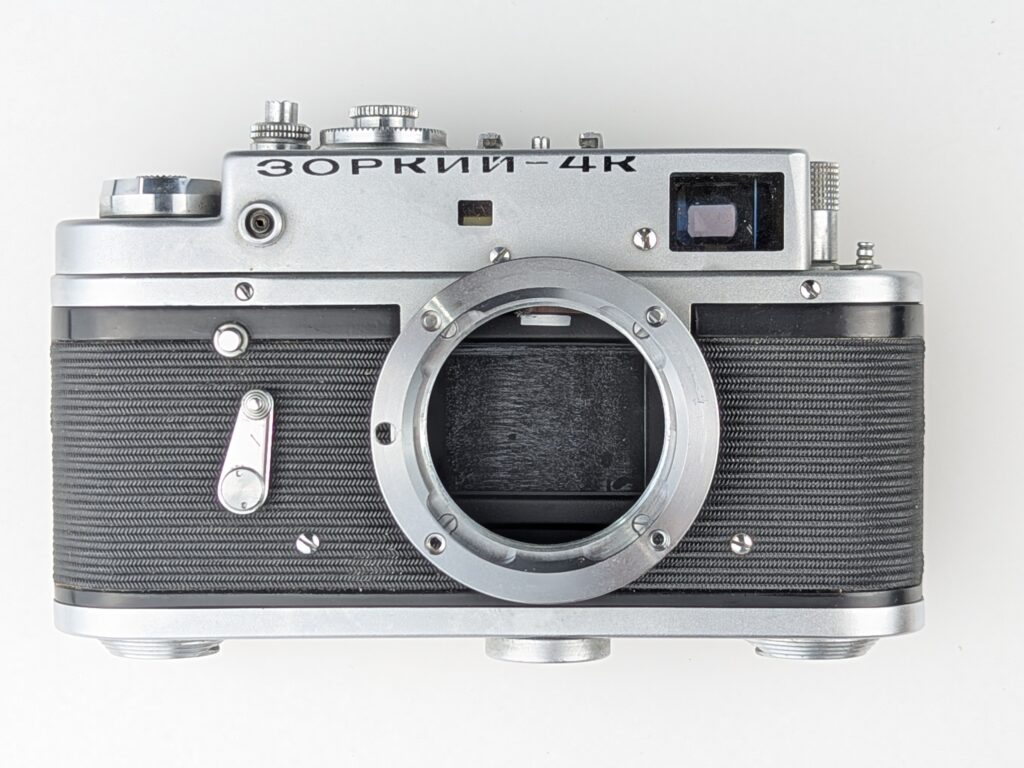
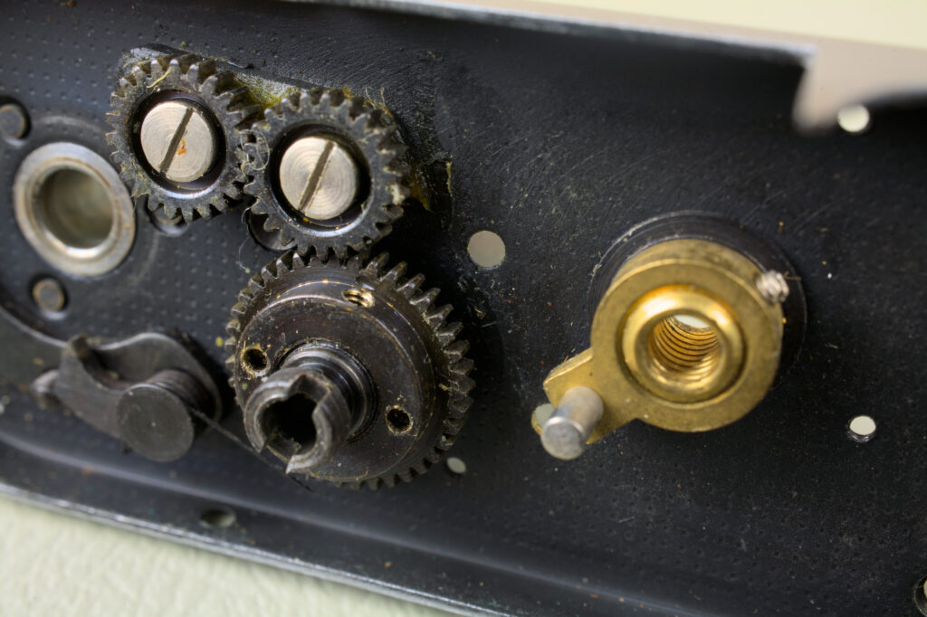
What I liked about the Zorki 4 or 4K is the plate I saw behind the mount. It has a boss that stands proud of the plate, so there is the opportunity to extract 1mm. Of course it is not as easy as just filing off the boss. The M mount is quite a bit bigger in diameter and uses a different bolt pattern. As a semi-retired machine designer and machinist, this was simply a chance to play with what I used to do professionally.
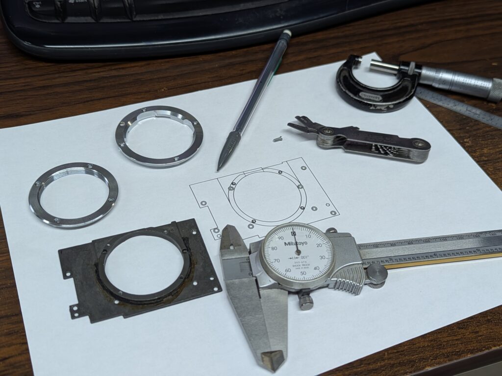
The front body needs to be modified for the larger mount and hold the lens release button. Luckily aluminum and brass are soft enough to be machined on a cheap Chinese-eBay CNC engraver. And I if my setup looks sketchy, believe me, it is way worse than you think! I’ve had this machine lying around for almost 15 years and it did a few simple positioning jobs and was even torn apart to donate one axis of movement for another task. It was never used as a CNC machine until it was reassembled for this camera. I wasn’t sure that it was even going to cut metal much less do it accurately, so I cobbled together everything it was missing from junk I had lying around. That is why it has a particle board table and 3D printed brackets mounting the spindle. I connected it via parallel port to a computer running LinuxCNC and while it is very slow, to my surprise it easily held 0.0015 inch (0.04mm) accuracy. So the barrier to entry for modding camera equipment is more about learning CAD/CAM and machining/work holding skills than the cost of equipment.
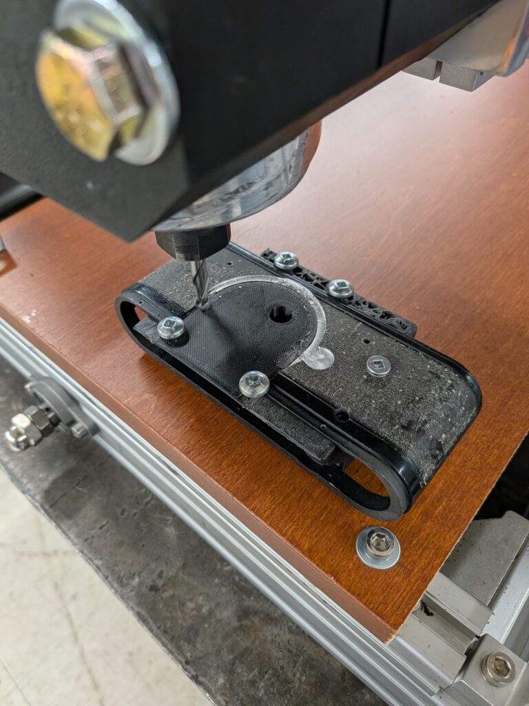
The 3D printed work holding shown under the body is horrible to post machine for accurate level and positioning. It also melts when the work piece gets hot. So I tested MDF fixtures. And while this is at least as janky as my machine, it works absolutely fine for machining one or two pieces. I’ve learned a lot about machining small, soft material parts; something I didn’t do during my regular course of work. And I am starting to see the potential for the little desktop machines on crowd funding platforms.
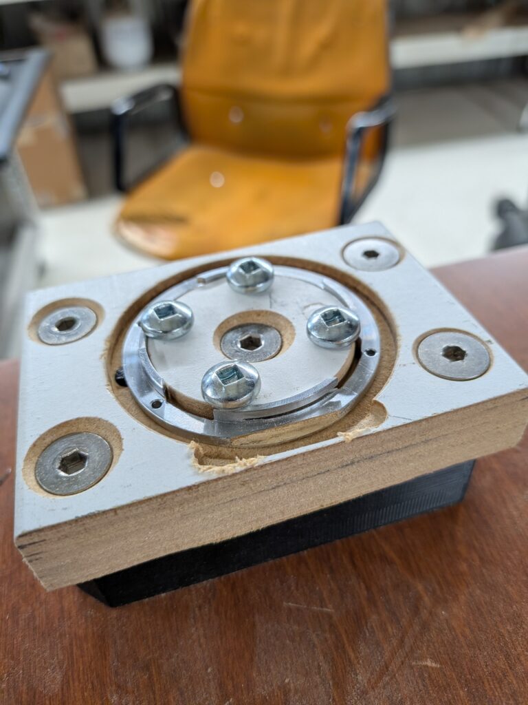
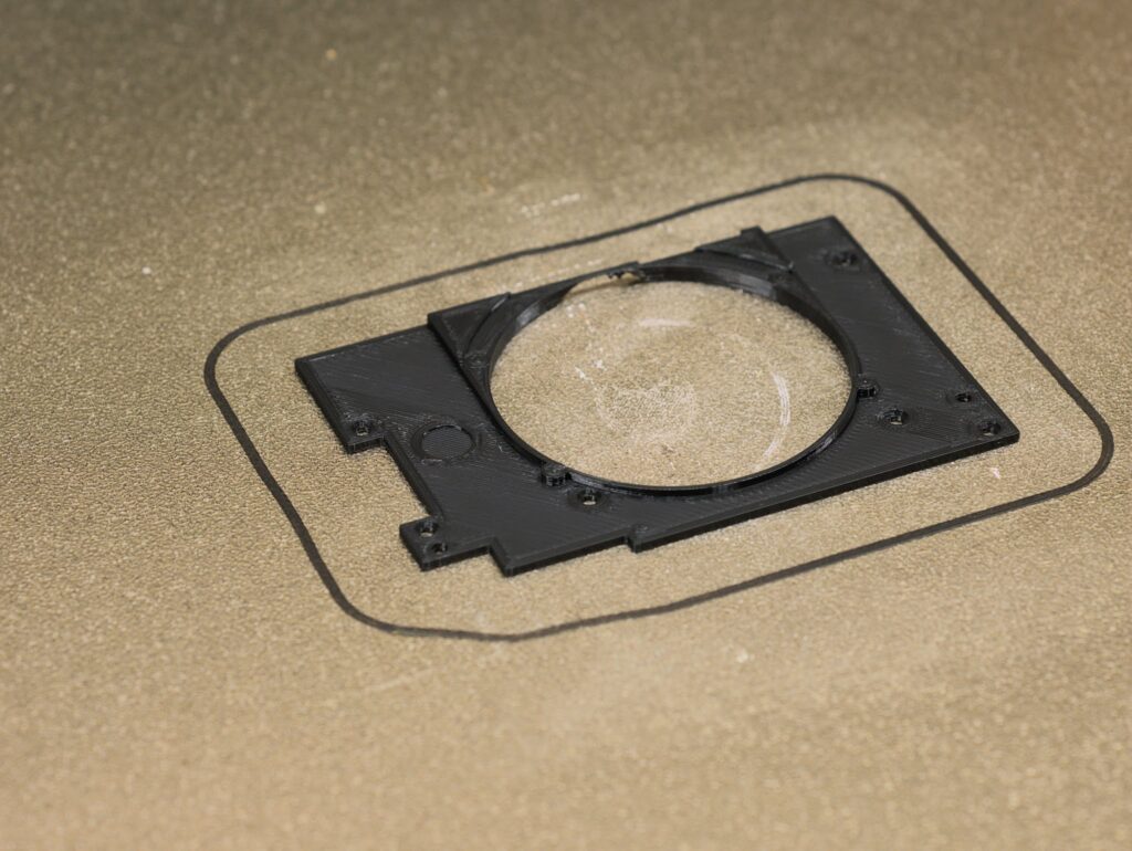
While I fully intended on machining the existing lens mount plate or make an aluminum one from scratch, the 3D printed part made for fit testing felt just fine when assembled. So at least for now, I’ve left it in.
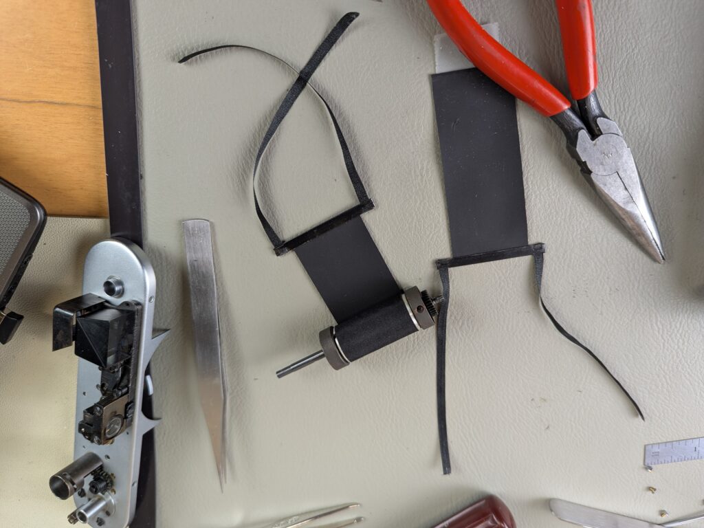
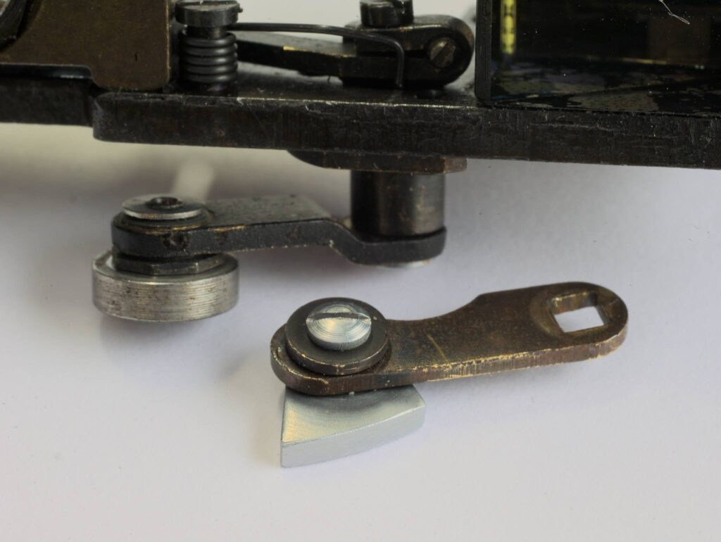
This is a mod that LTM re-builders can probably use with many Leica III based copy cameras but for sure with a Zorki 4. I bought the shutter curtain material and ribbons from a Japanese eBay store called nobbysparrow. He has everything to rebuild Leica III cameras. I asked for a cam follower and he had the roller one in the picture. He didn’t tell me the exact camera it was from but I’m pretty sure it is a Leica III variant. The weird pointy follower is the original Zorki and I know it will be inaccurate with a ramped cam lens, so I thought I would give the roller a whirl. I had to file the square hole a tiny bit to make it fit and as far as I can tell it works perfectly.
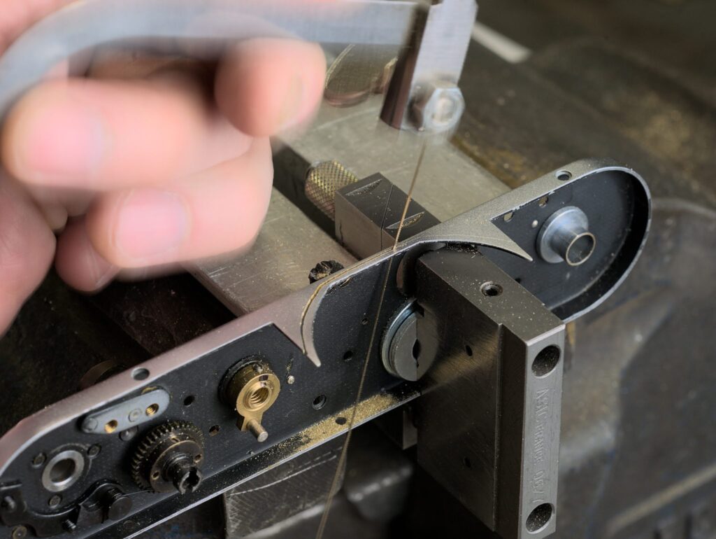
The top plate also needs to be modified to clear the mount. In the picture I am cutting it to fit snugly around the outside of the mount, If I did this over again, I would machine a shoulder on the back of the mount and make the cut smaller so the mount would overlap the top. It still looks okay and from my test pictures it does not leak light.
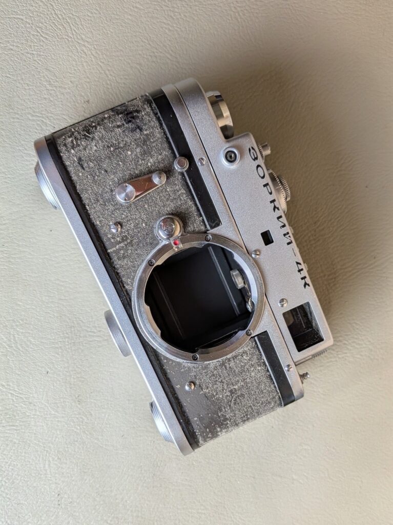
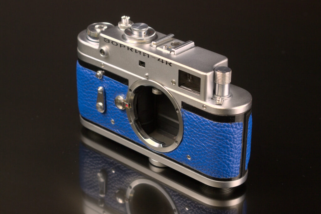
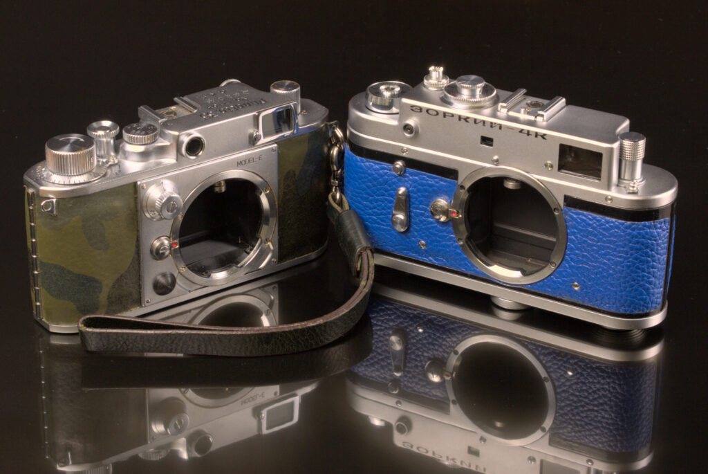
Here is the finished conversion job but I have not done any leather work. If you look closely inside the lens mount you can see where clearance was ground into the light shields with a dremel. This is the only part of the conversion I was less than satisfied with but it is only unsightly and does not leak light.
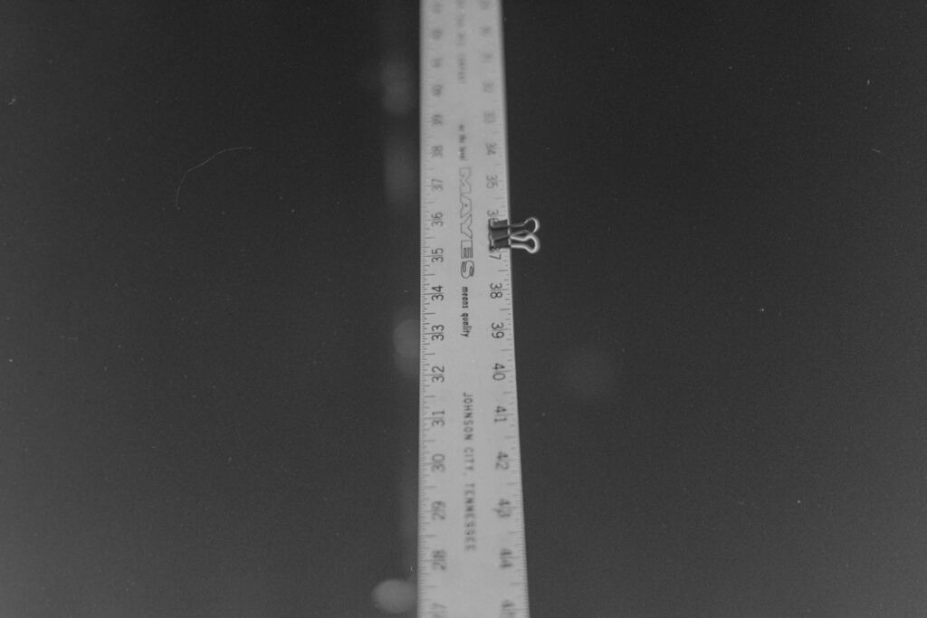
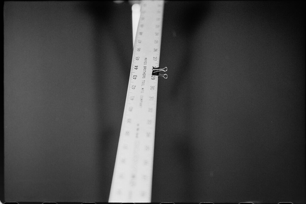
The rangefinder adjusted fine in both vertical and horizontal directions. I was pleasantly surprised to find out that the camera with the mod can focus down to 0.7m without any fiddling around. My focus testing was done with my Voigtlander 40mm f/1.2 @ f1.4 to clean up center sharpness and reduce field curvature. From this test picture the lens is standing about 0.002-0.004 inches too tall, assuming no field curvature (not true in my experience). I can correct this with a new 3D printed part but…
The focus was close enough to take it to a few events for test and learn some stuff about the camera… and it turned out my Zorki had a few more problem. The advance has both torn out the sprocket holes in my film on one shoot and then stalled and failed to advance the film after about shot 3 on another. From what I have read about Russian cameras, it’s not something to be surprised by.
Tearing the sprockets holes can be easily felt on the advance lever but the slipping is more subtle. So I 3D printed a ring to add a little more friction to the spool. This may make the tearing problem worse but I’ll see how it tests out long term. On my first few rolls it seems fine.
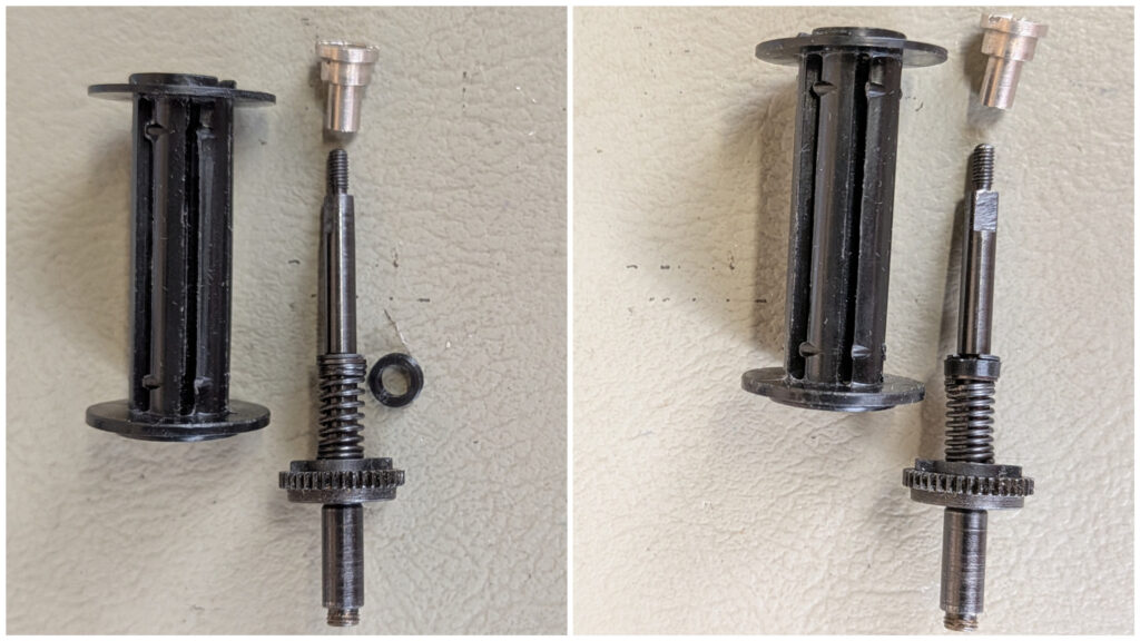
The gears in my system are imprecise and noisy. While the camera works, it behaves strange and is inconsistent. But I have come to appreciate that it is a benchmark of how bad a working camera can be. It has opened my eyes to qualities in other cameras that I had previously taken for granted. This will probably become clearer in Part 2 of this article. I’ve found fiddling with a camera when I’m out and about shooting helps me keep a sense of humor about photography. That said, this camera won’t get used when fiddling will make me grumpy.
Another problem it had was the visibility of the rangefinder patch. Even in good conditions, I was almost always losing the patch and unable to focus. At first I though the balsam joint in the main viewfinder prism had separated. After removing the prism by soaking in it acetone overnight and separating it into two pieces, I could see it was a poor mirroring job on the front prism half. The silver was terribly streaky and so thin in places that the light from the moving prism was not being reflected adequately. My first thought was “Now I’ve done it. This camera is toast”.
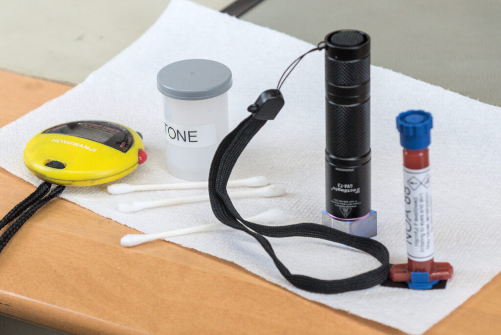
But after a bit of research on Google and watching a few videos on YouTube, I bought a mirror repair kit from Angel Gilding and UV curable optical glue from Edmund Optics. The silvering process is really fussy. Too much silver and the view finder is dark and hard to see through. Too little and the rangefinder patch doesn’t show up. Took about 5 tries before I thought what I had was as good as it was going to get.
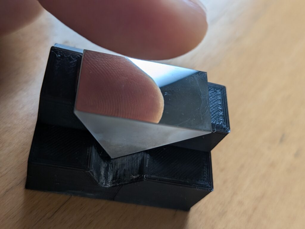
Using the UV cured glue was also new to me and it is also fussy. Partially curing the glue with a few seconds of UV light exposure sets the parts but the excess can still be cleaned up. That was a valuable lesson and made me happy I did not use a 2 part epoxy. Note that getting them apart again can’t be done with acetone anymore.
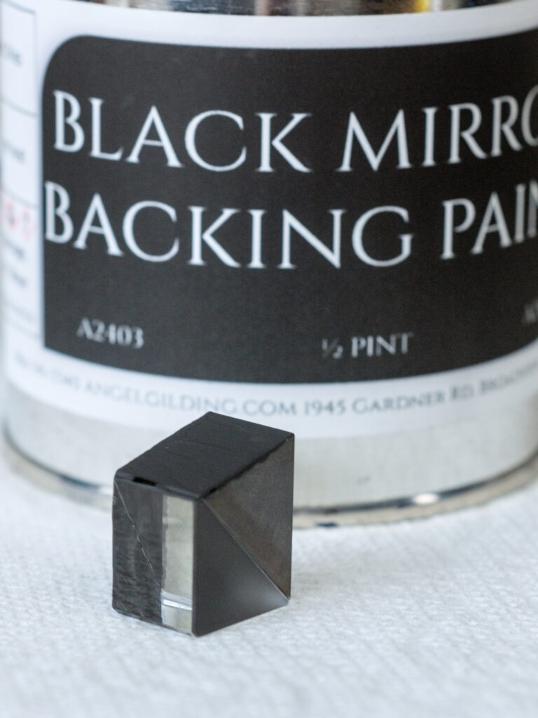
I then repainted the sides that need to prevent light ingress into the prism and cleaned up the splitter/combiner faces.
And finally, glued it back onto the rangefinder. This repair put another question in my head: Can I make a viewfinder beam combiner that will give me a 21mm angle of view? This is something I’m going to look into as I’d like to run my 21mm lens on film. I also find with the diopter adjusted for my sight the FOV of the viewfinder is probably tighter than 60mm by my guess.
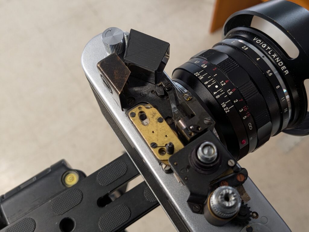
After all my repairs and much to my surprise, calibration went well and everything works! It’s not perfect: vertical alignment is perfect sometimes and off other times so the prism is probably not quite level. Whether it’s from me or the factory is anyone’s guess now.
I will say this prism fix is the most intimidating camera repair I have done to date. And while I wouldn’t want to do this all of the time, I am glad I didn’t just bail; which was my first reaction. Dad’s old adage comes to mind again.
The cost of the materials including freight, brokerage and the tariffs our glorious leaders have imposed was over CAD$300. Almost 10 times the original cost of my camera. So not something I would recommend for the typical Zorki rebuild. But if considered as a cost of education, quite reasonable in my opinion. Although I’m not sure I’ll be able use my education in the future… just like University come to think of it!
The last thing I did was convert the cold shoe to a hot shoe. I stole a center pin from an cheap optical trigger I had lying around, 3D printed an electrical isolation ring for it and machined the top and cold shoe spring so it would all fit. This was not a simple conversion as there is very little height to work with. It involved a jewelers file and a soldering iron to melt the printed ring into the cold shoe spring hole to make enough clearance that a flash could actually slide in.
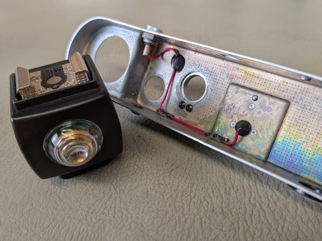
Sorry to those who are curious, for not providing more details on the prism fix and hot shoe conversion. I was too intent on my work to take pictures and the details probably would make the article way too long. If you want to learn more, you will just have to try for yourself. And on that note I will wrap it up here with a few samples.

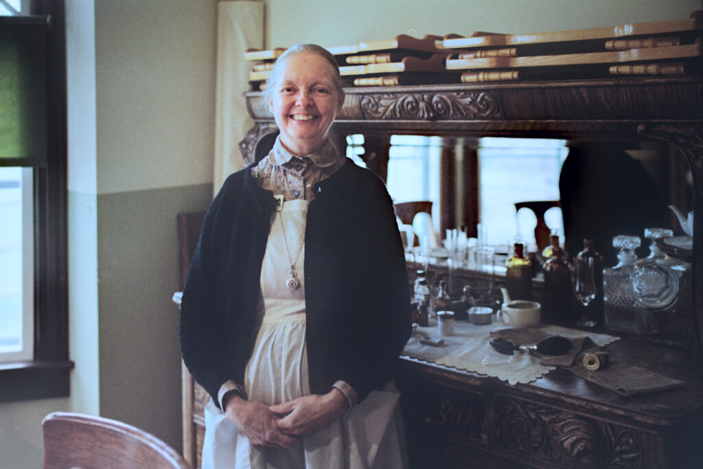
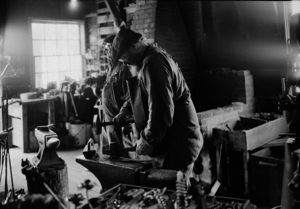
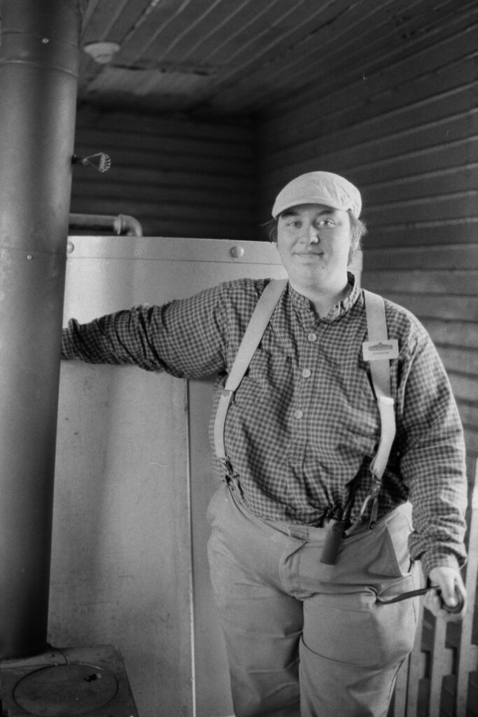
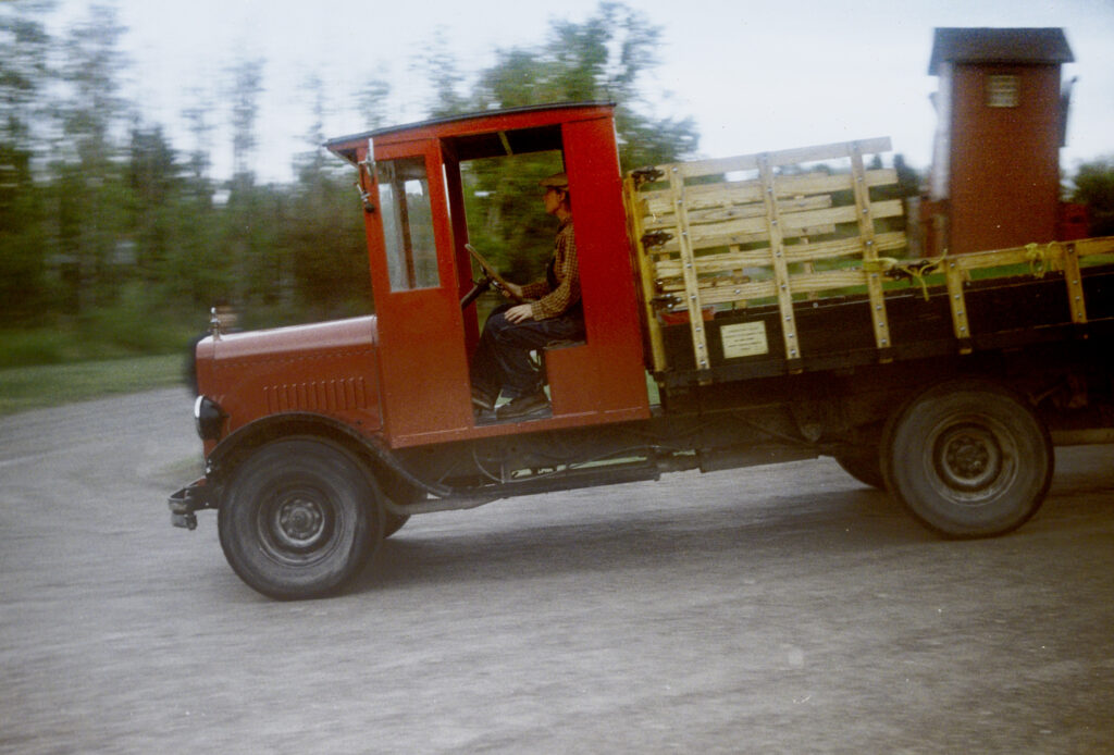
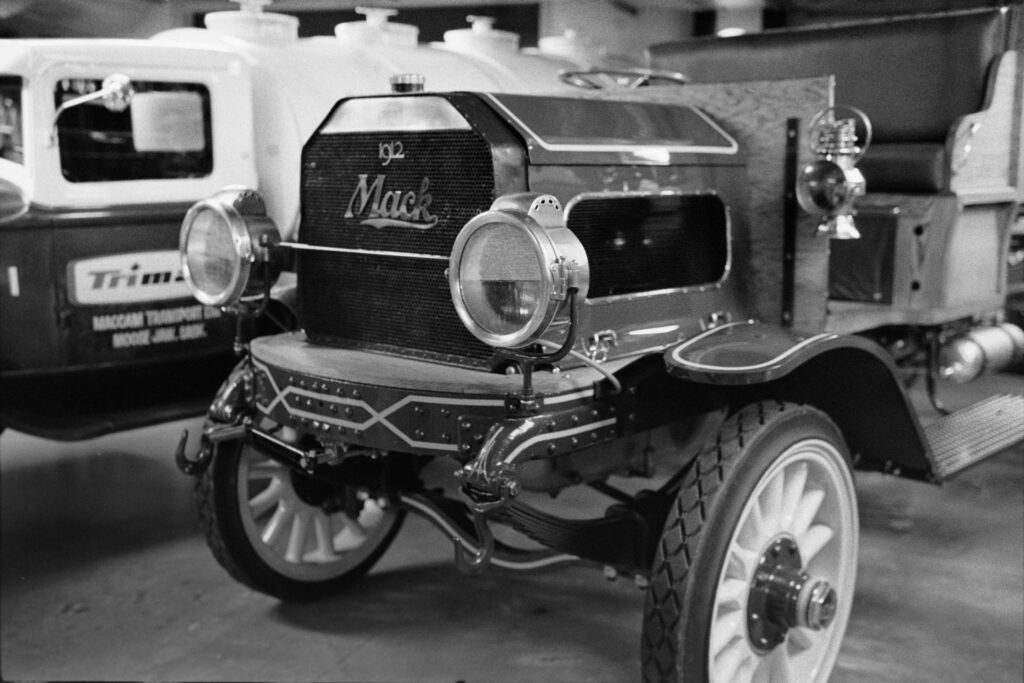

So when all is said and done, this is nicely repaired, lousy camera; a polished dog turd so to speak. But I like to embrace that about this camera. The modern “never miss a shot” cameras that can get great pics with the operator blindfolded may well be technological marvels but I find them somewhat joyless. Getting this camera to where it is has already brought me joy and I have a feeling keeping it running into the future will too. Getting nice images with a meter-less, manual focus camera takes practice. And while there are times that a misbehaving camera will make me grumpy, the rest of the time I’m happy to see the results of something screwing up. After working with cameras that give consistent results over a long period, I simply get bored. I like to laugh at my mistakes now and always enjoy seeing happy accidents that for whatever reason, have turned out more interesting than the shots that I classify as my sea of consistently boring, technically great images.
Oh by the way: Can a LTM camera be converted to M mount? Yes, it can. I couldn’t have answered that question if I had done the practical thing and bought an M mount camera.
Share this post:



Comments
Walter Reumkens on Changing LTM cameras to M Mount and learning camera repair (Part 1)
Comment posted: 26/10/2026
I couldn’t have done that; I’d have spent the whole time out taking photos with my Zorki 4k with LTM. :-)))