If X is good and Y is good, then X and Y combined must be even better. Out of this misguided reasoning have emerged such unholy inventions as the beer-tap hat and ice-cream fries. But sometimes, such combinations really do work – and I guess you don’t know until you try.
I’ve been obsessed with pinhole photography for a while, making my own cameras from cardboard boxes, cake-tins and the like. And last year, I got into stereoscopy – the creation of images which look 3D when seen through a special viewer (or even with the naked eye, if you can master the trick). So I guess it was only a matter of time before I tried my hand at combining the two. Enter: the homemade stereoscopic pinhole camera.
In this post, I’ll briefly describe how I made my stereoscopic pinhole camera from a cardboard box and other simple, costless materials. I’ll also share a few images made on three different media: photographic paper, B&W film and instant film.
Pinhole 101
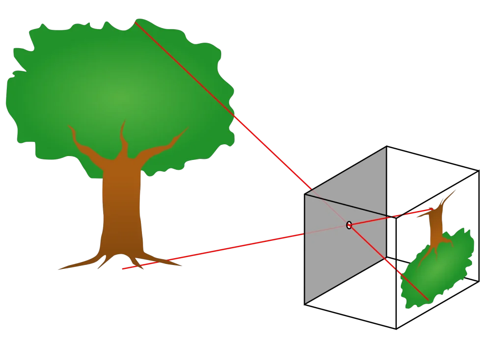
A pinhole camera makes images without the use of a lens. It is just about the simplest camera imaginable – an otherwise light-tight container with a tiny hole which admits light. Rays of light passing through the hole project an inverted image inside the camera. That image can then be recorded using light-sensitive film, paper or even a digital sensor (the diagram below may be more helpful than my description).
Pinhole images have a few typical characteristics. Since the image-forming mechanism is so simple, pinhole photos are generally less sharp than ‘lens cameras’. Because of the tiny aperture (my camera is around f/100), pinhole photos have virtually infinite depth-of-field. Finally, the small aperture entails longer exposure times, so pinhole photos often exhibit motion blur and other ghostly effects. Some like the effect; ‘sharpness is a bourgeois concept,’ said the inimitable Henri Cartier-Bresson. But some don’t, and that’s okay too.
Homemade pinhole cameras
One of my favourite things about pinhole photography is creating homemade pinhole cameras. In fact, all my pinhole cameras are made from household waste such as cardboard boxes or cake-tins. This is partly because I lack skills like woodworking or 3D printing, but also because it’s a great way to upcycle. And since they require no special skills, anyone can make these cameras.
I name all my pinhole cameras. They take better photos if you give them a name (scientific fact). My stereoscopic pinhole camera is called ‘Cyclopin’ – a pun on Cyclopean. A Cyclopean image is the 3D mental image of a scene created by the brain by combining the images received from both eyes; this process is crucial to stereoscopy, and stereo vision more generally.
Making the pinholes
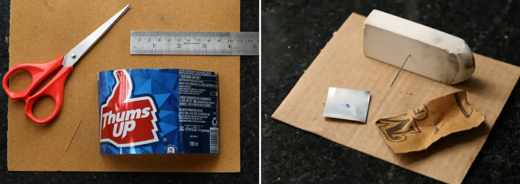
Being a stereo camera, Cyclopin takes two simultaneous images, so naturally it needs two pinholes. Thin, opaque materials are good for pinholes. The ones for Cyclopin were made – as with most of my pinholes – by cutting small squares of aluminium from a soda-can, and drilling tiny holes in them with a needle (the process is described in more detail in this article). I then taped the metal squares onto holes cut in the cardboard box lid.
For a stereo camera, the two pinholes need to be around the same size. If not, one would let in more light than the other, and the two halves of the stereo image would have different exposures.
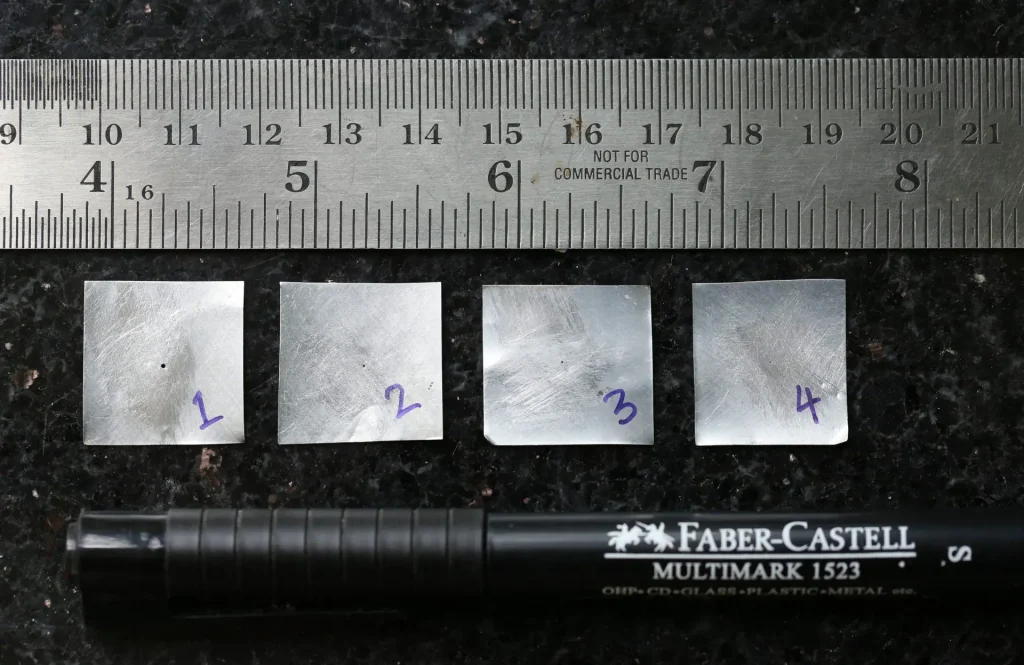
When I get down to making pinholes, I tend to make a dozen or so at one go, then I measure them and note their diameters for future use. For Cyclopin, I simply picked two from my collection which are similar in size (around 0.48mm in diameter).
There are various ways to measure pinholes. I described three different methods in this article (I tend to use the DSLR method, but they all do the job).
The same article also explores (in excruciating detail) the question of optimal pinhole size – ‘optimal’ in this case meaning that which produces the sharpest image. I have an academic interest in the optimal-size question, but when it comes to actual use, I’m a lot more lax. Many of my pinhole cameras don’t have the optimal size (I once made a pinhole camera from a biscuit, which is very far from optimum).
Measurements
The cardboard box I used for Cyclopin has a depth (focal distance) of 50mm, which entails an optimal pinhole diameter of 0.33mm. The pinholes I used are around 0.48mm, simply because I happened to have two in that size. The non-optimal size does make them slightly less sharp, but it’s not a big deal for me. Pinhole images – even ones made with ‘optimal’ pinholes – are inherently unsharp, and that’s part of their beauty.
The effective aperture of the camera is 50/0.48 ≈ f/100. The image area is 14.8 × 7.2cm, but this being a stereo camera, two images (7.2 × 7.2cm each, with a 0.4cm separation in between) are recorded side by side on photographic paper or film.
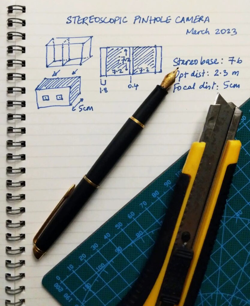
The ‘stereo base’, i.e. the distance between the pinholes, is 7.6cm. The 1/30th rule, described in this post, indicates that the optimal distance for a stereo subject would be 7.6 × 30 = 228cm (~2.3 metres). If a subject is closer, it will look ‘hyper’, i.e. appear to have exaggerated stereo depth, while subjects which are further away will have too little depth.
Some cameras have an adjustable stereo base, but on Cyclopin, it is fixed (though there’s a workaround, which I will come to later). This means that the optimal subject-distance is also fixed. But as with optimal pinhole size, I don’t lose sleep over stereo depth. If I see an interesting subject which happens to be closer or further away, I’ll go for it.
Modifying the box
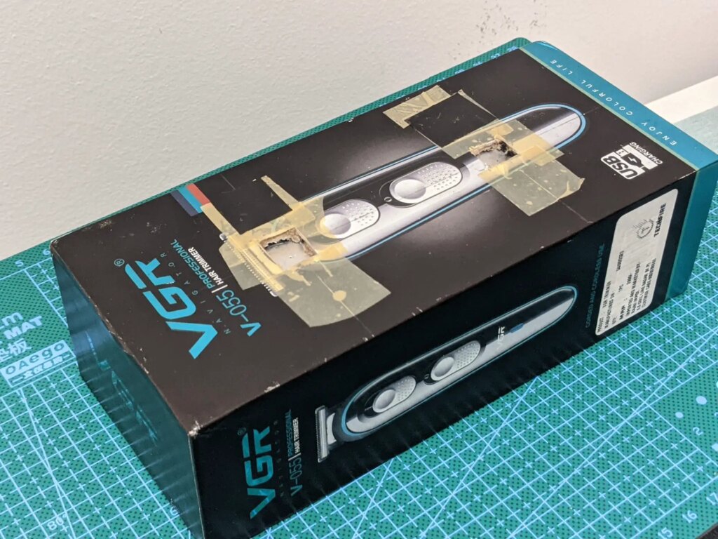
Cyclopin, as I said, was made from a cardboard box. The box came with a hair-trimmer, which my brother bought during covid lockdowns. It’s similar to a smartphone box. Such boxes, being relatively robust and light-tight, are very well-suited for pinhole cameras.
In the next photo, the box is nearly intact, except I’ve ‘installed’ the pinholes.
These boxes have two parts: let’s call them tray and lid. The tray (bottom part) is slightly smaller, and fits snugly inside the lid.
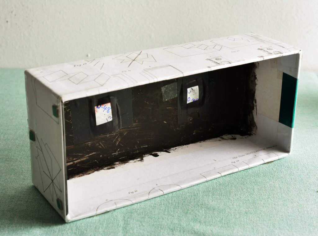
First I painted the inside of the box black, to prevent light bouncing around inside and affecting the image. I then measured out where the film or paper would go on the inside of the tray, cut two corresponding holes in the lid, and taped the pinholes to the inside. Parts of my build are clearly somewhat rough-and-ready, but I tried to position the pinholes as precisely as I could (aligned with the centre of each image). This ensures that the stereo images are nicely aligned straight out of the (literal) box, requiring fewer adjustments in post.
The next photo shows the pinholes from the inside. Black tape reduces the likelihood of light leaking around the metal square.
I actually made a mistake here, which you would do well to avoid. The pinholes can either be on the tray bottom, with the film or paper being on the inside of the lid – or vice versa. For mono pinhole cameras, which I’ve made many more of, it doesn’t really matter; you can do it either way. But if you’re making a stereo pinhole camera, for reasons which will soon become obvious, the former (pinholes on the tray bottom) is a better choice.
I didn’t think this through, and of course, Murphy’s Law ensured that I did it the wrong way round (pinholes on the lid). This is not the end of the world, just a slight complication. Here’s why.
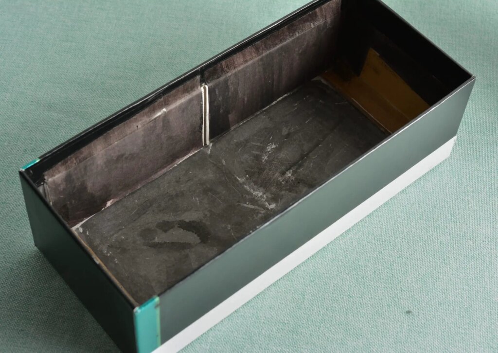
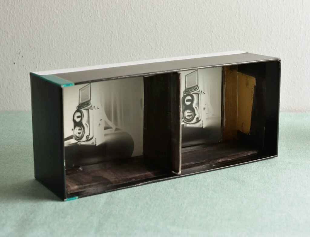
A stereo camera like this one needs a vertical partition between the two image areas; otherwise, the images from the two pinholes will overlap. That partition needs to be inside the tray. If the partition is inside the lid, the tray obviously won’t fit into the lid.
Because I made my pinholes on the lid, the film or paper has to go on the inside of the tray. But now the partition is in the way. So I realised I have to make a removable partition. The next three photos show how this works.
First, I pasted cardboard pieces inside the two long edges of the tray, creating a pair of grooves for the partition to slide into. In the photo below, the groove is in white (there’s another one on the opposite side as well).
The next photo shows how the paper (or film) fits on the inside of the tray. For illustrative purposes, I used a piece of exposed paper (paper negative). You can also see the one of the grooves below.
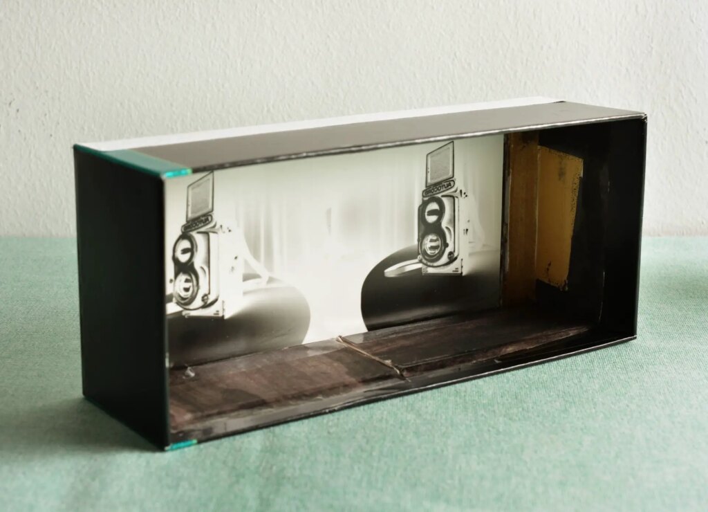
Finally, the photo below shows how the vertical partition (a piece of cardboard, painted black) slides into the groove, neatly separating the two image areas.
So after loading a new piece of paper or film inside the camera, I need to slide the partition in. This could be avoided, as I said, by making the pinholes on the tray bottom, with the film or paper being on the inside of the lid. The vertical partition could then be permanently installed inside the tray.
Shutter and ‘viewfinder’
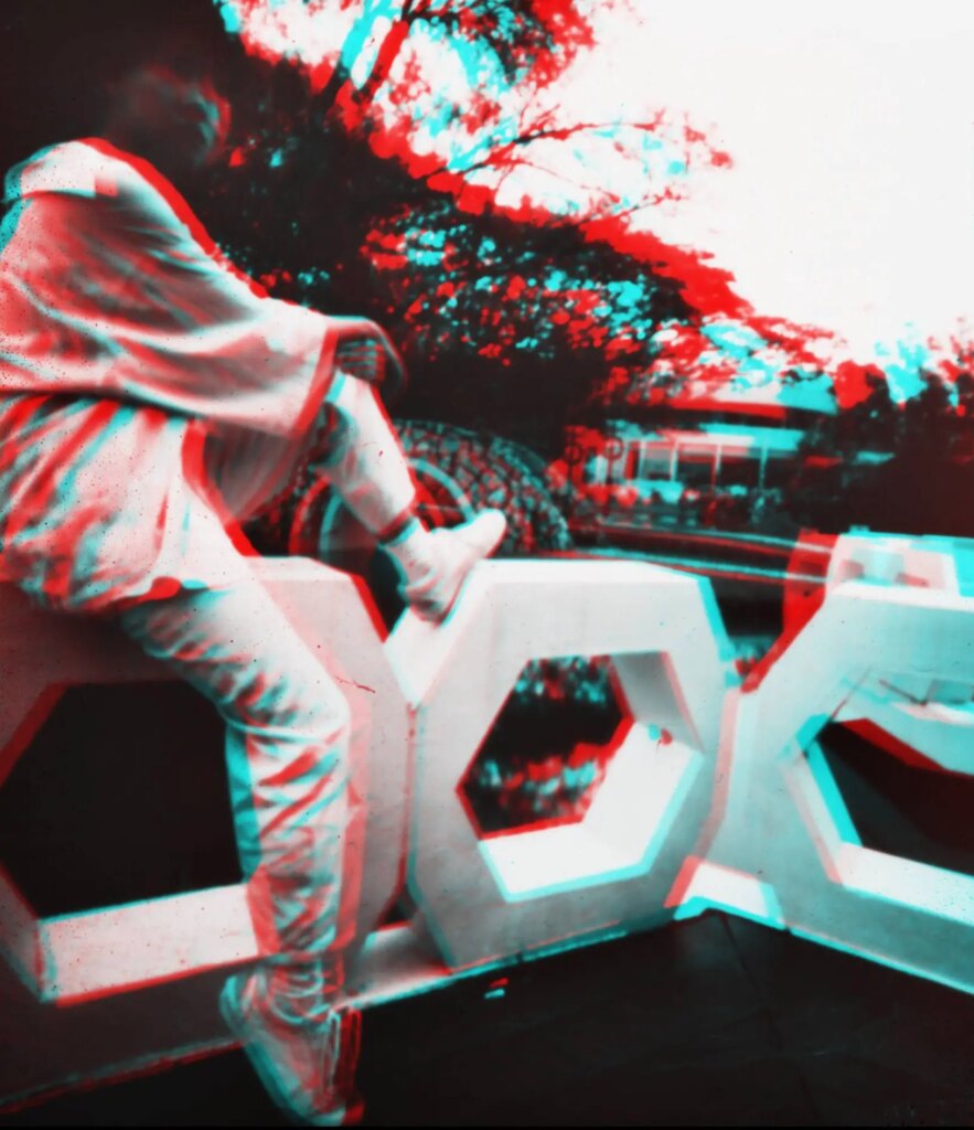
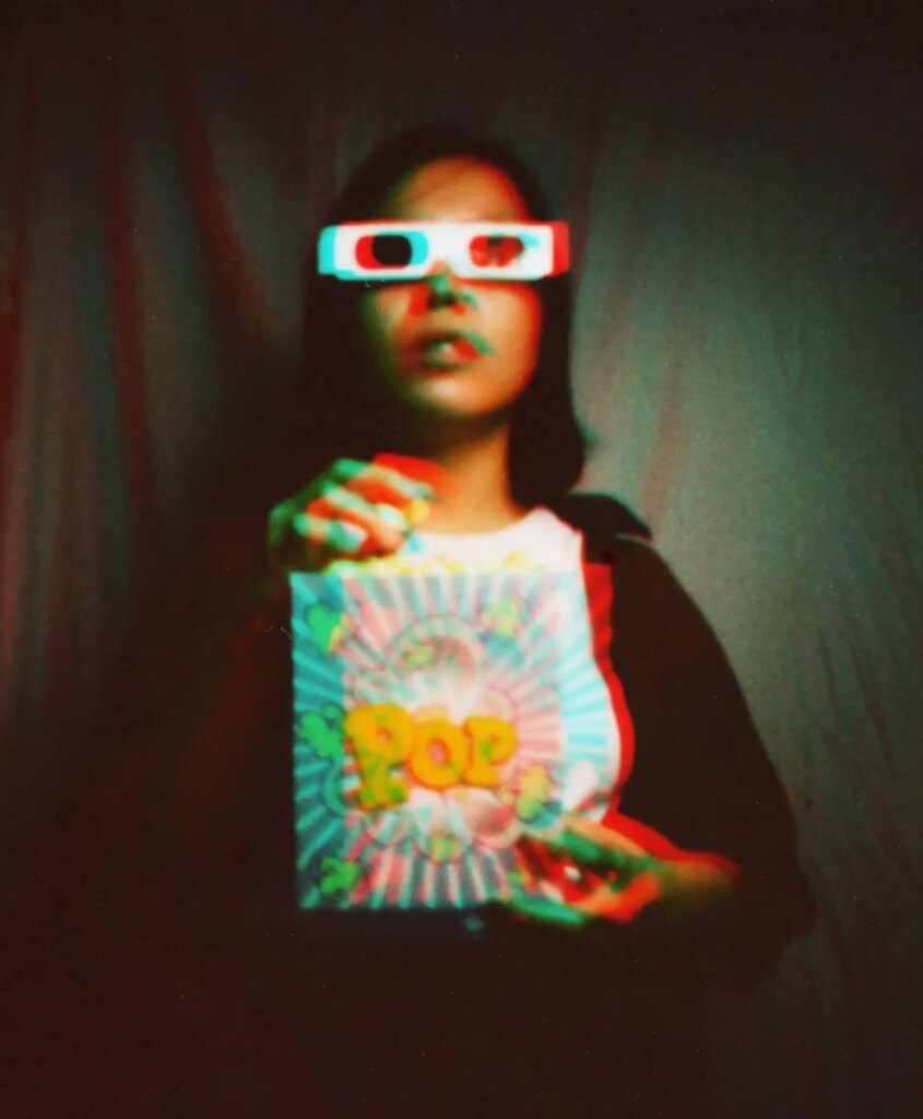
A stereo camera needs two shutters. I decided to paint them cyan and red – a reference to the cyan/red stereo glasses used for viewing anaglyph 3D.

There are many ways to make a pinhole camera shutter. I use a simple cardboard shutter which I designed myself (I hesitate to say ‘invented’, because others may have come up with this design before me; I don’t know). It has two layers, shown in the photo below: the shutter layer (top), and the frame (bottom).
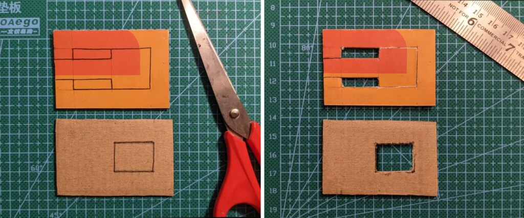
I stick the shutter layer to the camera body first, and then the frame above it. The shutter layer has a T-shaped moving part which blocks the pinhole. For convenience, I attach a pull-tab (made of tape) to the T-shaped part. To open the shutter, you simply pull on this tab. To close it, you push it in. In the photo below, one shutter is open while the other is closed.
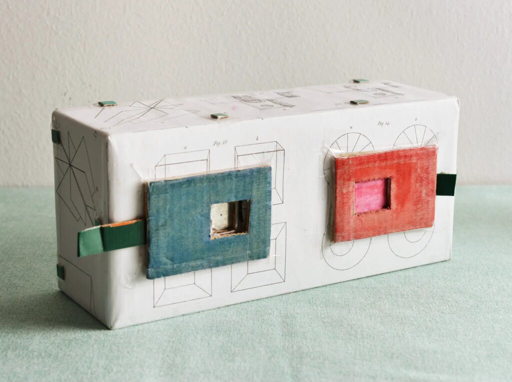
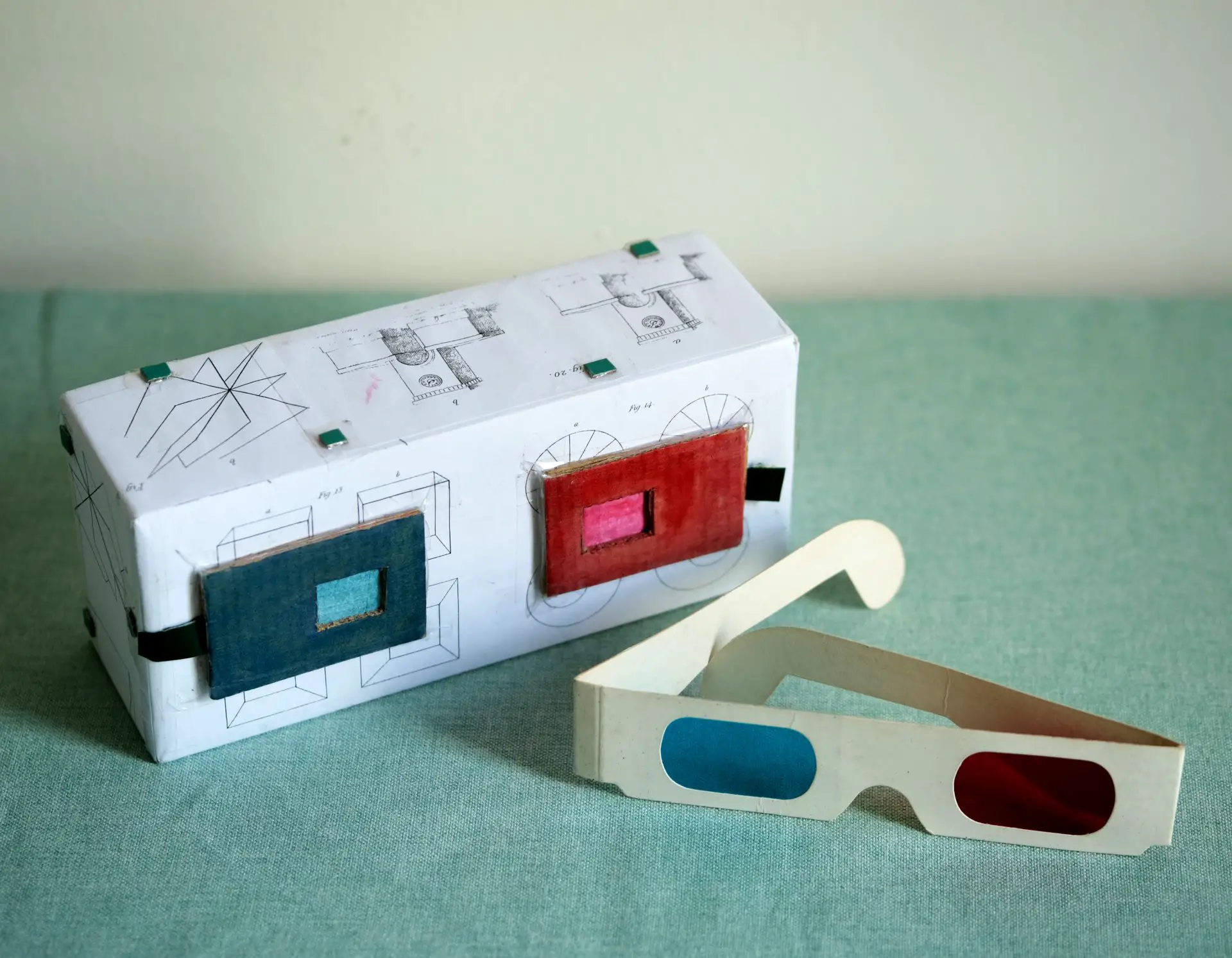
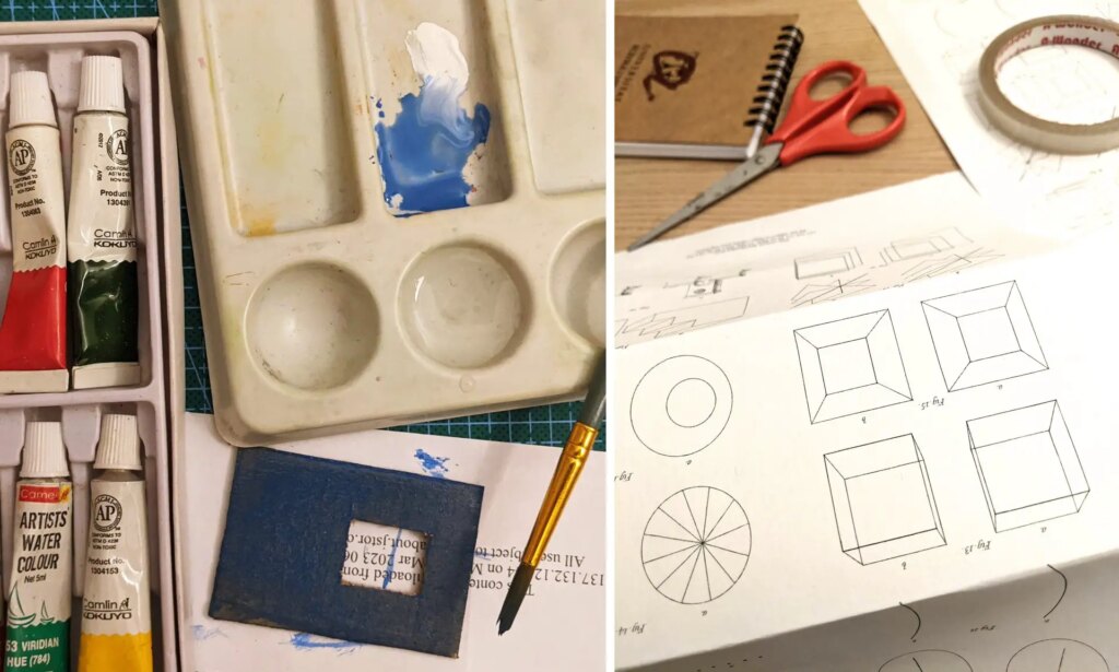
While I was at it, I thought I’d decorate the camera a bit more. So before attaching the shutters, I covered the lid with paper, on which I had printed diagrams from Charles Wheatstone’s pathbreaking 1838 paper where he described the principles of binocular vision.
For the back (i.e. the bottom of the tray), I printed an old drawing of a camera obscura.
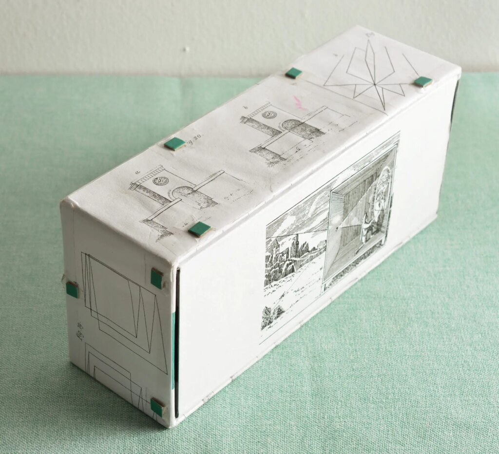
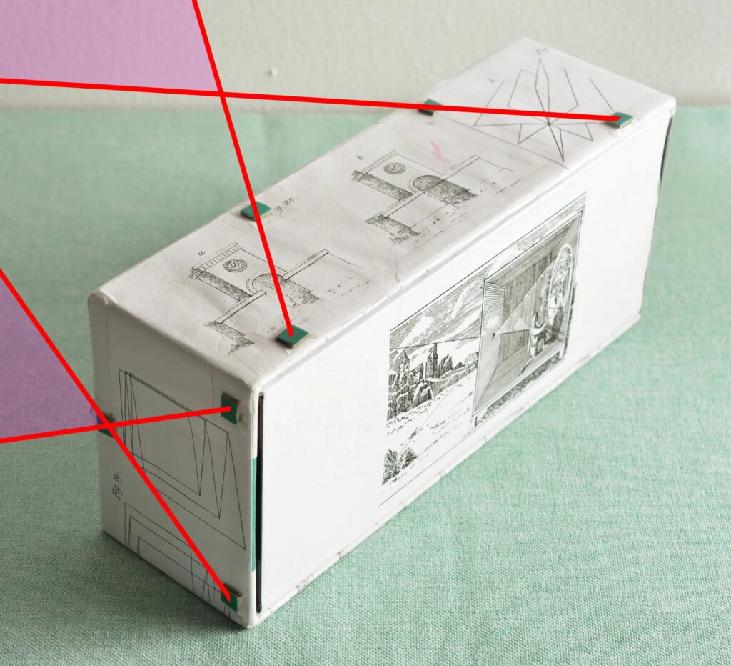
See the little teal squares in the photo above? They’re the Cyclopin’s ‘viewfinder’. Imagine sightlines passing through the squares, and you’ll get an idea of how much of the scene will be in the frame. Since light travels in a straight line, the sightlines are defined by the location of the pinhole (front) and the edge of the image area (back); I simply position the squares accordingly.
In the image below, I added red lines to show the (imaginary) sightlines. The pink areas show the angle of view – how much of the scene will be included in the stereo image.
Sample images
Finally, it was time to test the camera. I’ve taken pictures on three different media: photographic paper (used for darkroom printing), B&W film and Instax film.
Photo paper
In the darkroom, under safelight, I cut a 14.8 × 7.2cm piece of Ilford MG RC photo paper and loaded it in the camera. Photo paper has an ISO of ~6, and the camera, as I mentioned, has an aperture of ~f/100. So exposure times, even in bright daylight, are quite long. Due to the tiny aperture, most people use pinhole cameras for landscapes, architecture and still-life, but I like taking photos of people. Thankfully I have indulgent friends like Kwang (below), who will sit still for the inordinately long exposures required for my pinhole experiments.

The photo above is a behind-the-scenes shot taken with my phone. My camera (bottom right) is secured to my tripod with rubber-bands. The exposure time was around 30 seconds.
I developed the paper negative in Fomatol-P. The photo below shows the paper negative, and below it, the image inverted in Photoshop.
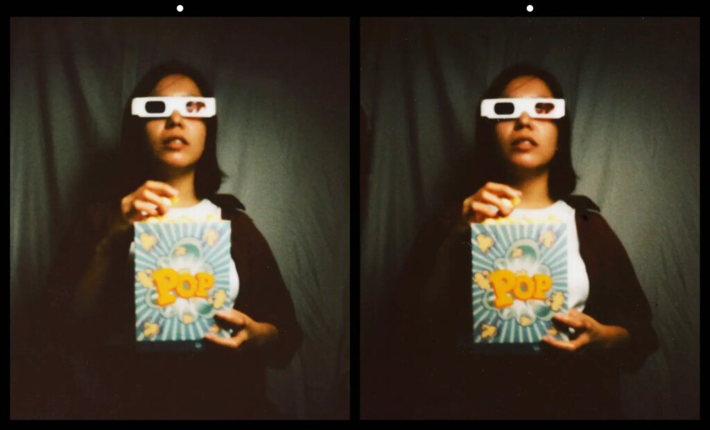
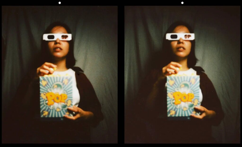
Next up, three stereo versions of the same image, formatted with Stereo Photo Maker.
B&W film
I also took a photo on B&W medium-format film (Foma 100). Unlike photo paper, panchromatic film can’t be handled under safelight. So I had to cut off a piece of film in the right size, and load it in complete darkness. This is obviously a tricky procedure, and not something I want to do repeatedly.
I’ve made other (mono) pinhole cameras where you can load a whole roll of film, but that’s a more complicated build – you need to make a film-advance mechanism and a frame counter. I didn’t go down this road with my stereo camera, as I mainly plan to use it with photo paper. Using film was more just an experiment – a proof of concept, if you will.
The image below is formatted for parallel view.

As a proof of concept, it works, but that’s about it; I’m not a fan of this photo. The subject was too close, so the stereo is too hyper for my taste. Plus I developed it in Fomatol-P which is a paper developer, and as a result, the tonality is also not great. I haven’t bothered to make cross-eye or anaglyph versions of this image; believe me, you’re not missing much.
Instax
I had not planned to shoot Instax film in this camera, but coincidentally, it turned out that the image area is well-nigh perfect for two sheets of Fuji Instax Square. So of course I had to try it.
The process I use for shooting Instax film in other (non-Instax) cameras is similar to that described by Jessica Bellinger in this video. At some point I’ll write it up as a proper article, but in short:
- Slide an Instax sheet out of the cartridge.
- Load it in some other camera.
- Expose the film (I get good results rating it around ISO 800).
- Take it out of the camera and slide it back into the cartridge.
- Load the cartridge into an Instax camera.
- Cover the Instax camera lens and make a blank exposure.
Steps 1, 2, 4 and 5 need to be done inside a changing bag, or in complete darkness, otherwise it will ruin the Instax film (or possibly the whole cartridge). After you make the blank exposure (step 6), the film is automatically ejected from the Instax camera as usual, and this is what causes it to be developed (until then, it’s an exposed but undeveloped piece of film).
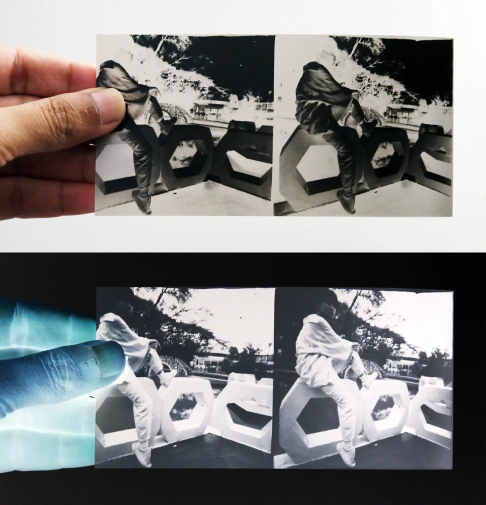
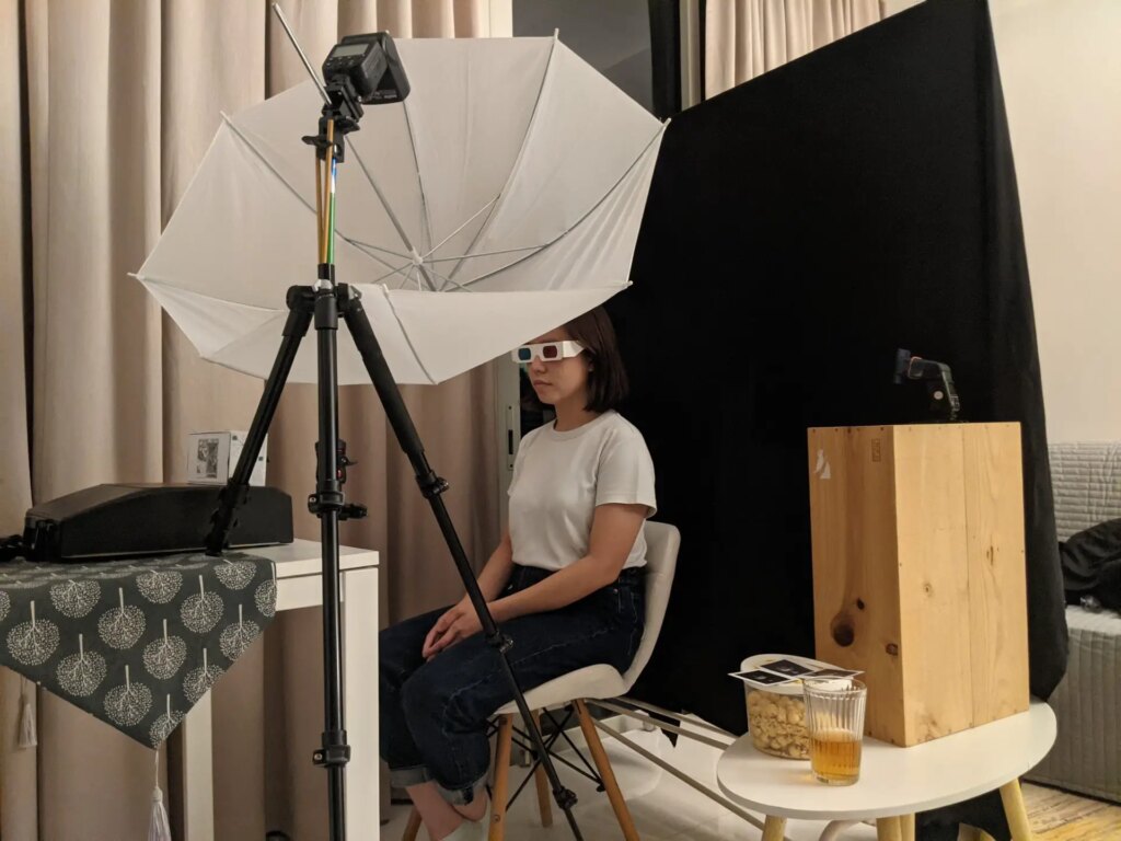
Instax film is relatively fast (~ISO 800, as I mentioned), but because Cyclopin is only around f/100, it still needs plenty of light. The lighting for this photo was a Godox TT-600 flash fired at full power, twice, through an umbrella modifier. My friend Pearl had to hold still so that the two flash exposures wouldn’t result in a double image.
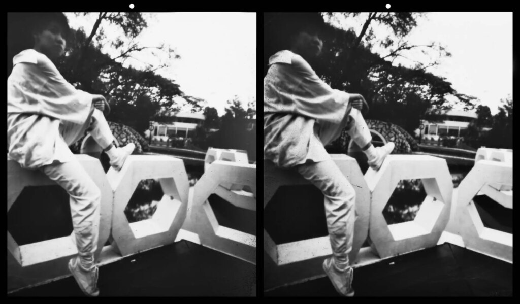
Here are the two Instax photos laid side by side. I was pleased to see that I could directly free-view the photos as a 3D pair. This shows that the stereo alignment is quite good – especially considering it’s a homemade camera!
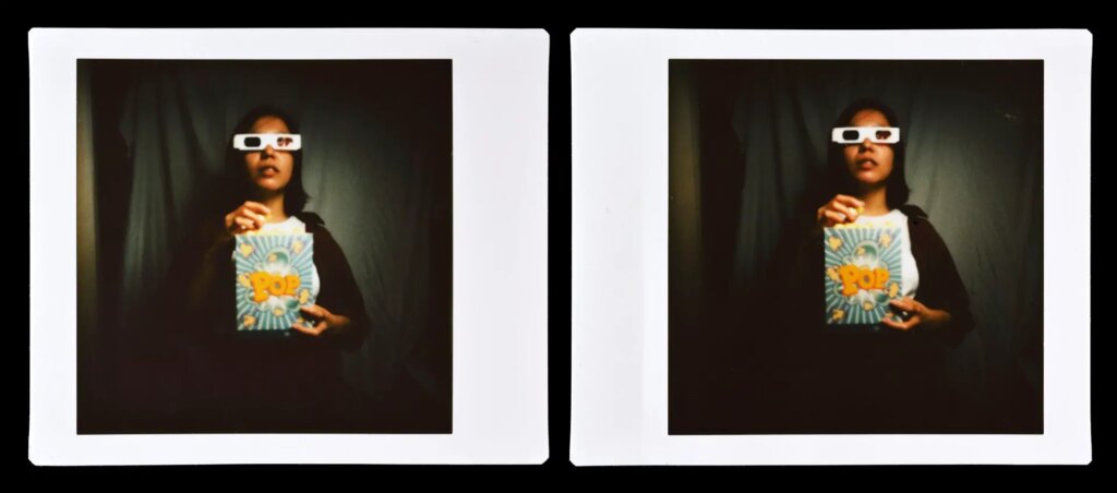
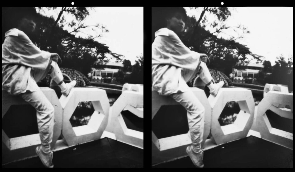
Next up, stereo versions of the same image, formatted with Stereo Photo Maker.
Final thoughts
And that brings us to the end of my experiments so far. I’m sure some of you have experience with pinhole photography, or stereo photography, or both. If not, I hope my post inspired you to try such experiments. Or maybe you’re like “No way, this is far too troublesome and slow!” In which case, you may gain a renewed appreciation for how nice and convenient your ‘normal’ camera is.
And that too is a positive outcome, in my book.
Thanks for reading, and feel free to check out my Instagram!
Share this post:

Comments
Lance on Cyclopin: My Stereoscopic Pinhole Camera Made from a Cardboard Box
Comment posted: 26/06/2023
Comment posted: 26/06/2023
Vlad Serebryany on Cyclopin: My Stereoscopic Pinhole Camera Made from a Cardboard Box
Comment posted: 26/06/2023
Comment posted: 26/06/2023