Two main factors determine how a pinhole camera “sees” – that is, whether its angle of view is wide, normal or tele. The first is the sensor size (throughout this post I’ll use ‘sensor’ as a general term for any photosensitive surface, including film, paper or digital sensor). The second is the focal distance (the distance from the pinhole to the sensor).
These three variables – angle of view, sensor size, focal distance – are interrelated. In this post, I’ll explain in basic terms (no complex maths) how these variables affect one another. But mainly, I want to share a Excel calculator which I made to help with pinhole design – along with photo samples, to show that it works.
So what does this calculator do? Essentially, you can enter any two variables into the calculator, and it will tell you the third. Let’s say you have a box which is 8cm wide (this being the focal distance). And you want to load it with 4×5″ sheets of paper or film. The calculator will tell you that the angle of view will be similar to that of a 21mm lens on a full-frame camera – that is, pretty wide.
Another example. Say you want to take 6×9cm images on 120 film, and you want a more “normal” angle of view, like a 50mm lens. The calculator will tell you that your focal distance needs to be 12.5cm, and you can design your camera accordingly, or look for a box that size.
The calculator I’m referring to – a Google spreadsheet which I’ve linked to and explained below – is for designing the pinhole camera body. Another common calculation is the optimum pinhole size, which is a function of the focal distance. The latter is covered in a previous post. I also made a calculator for optimum pinhole size, which is under a different tab in the same Google spreadsheet – again, see my previous post for a full explanation of it. I did it this way because I prefer to keep the two calculations separate – first design the camera, and then pick the optimum pinhole for it.
The motivation
One of my favourite things about pinhole photography is making homemade pinhole cameras. In fact, all my cameras are made from household materials like cardboard boxes, cake tins, etc. This is partly because I lack skills like woodworking or 3D printing, but also because it’s a great way to upcycle household waste. And since they require no special skills, anyone can make these cameras.
And one of my favourite things about homemade cameras is that – with some constraints (materials available, practical considerations, the laws of physics…) – you can design them exactly how you like.
For one, you’re not limited by commercially-available film formats and sizes. My friend María Luisa cut a tiny piece of photo paper to fit inside a pistachio nut which she fashioned into a pinhole camera. Citlalli made a superpanoramic camera which takes 6×18 images on 120 film, wider than any commercially-produced medium-format camera that I know of. And Vera Lutter has turned entire rooms into pinhole cameras, exposing images on wall–size sheets of photographic paper.
You also have control over the angle of view. For this photo on my Instagram, I used a camera with an angle of view similar to that of a 16mm lens on a full-frame camera. Nick Dvoracek, on the other hand, has made cameras with telephoto focal lengths – relatively rare, but totally possible!
Making pinhole cameras by trial and error is a lot of fun, and an easy entry-point into the hobby. But soon, I became more curious about the maths behind it. For example, how would I go about designing a more wide-angle camera, or how would my images change if I loaded a camera with 120 film instead of 4×5″ paper?
MrPinhole has a nice calculator for this sort of thing, but I wanted one for my specific needs, that is, suited to how I design pinhole cameras. There was nothing for it but to make my own. And having made one, I thought I’d share it here, in case anyone else wants to use it – or better still, improve upon it.
But first, the basic science.
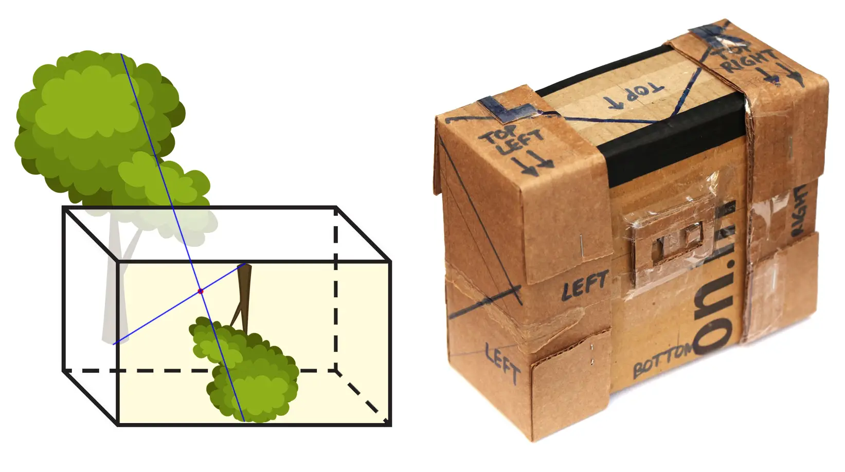
Pinhole geometry
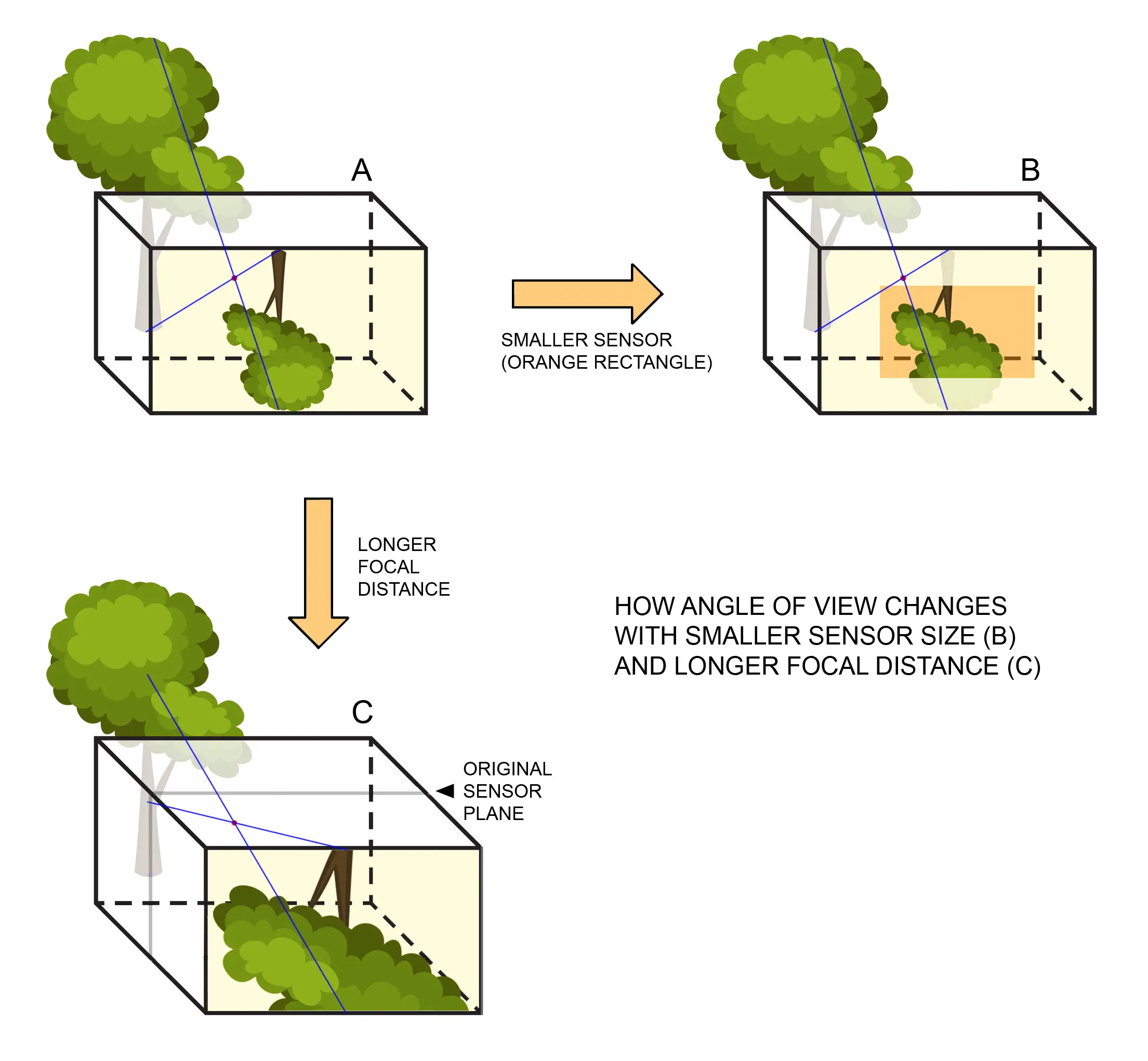
The diagram above shows pretty much all you need to know. With a smaller sensor (B), the angle of view is reduced. The image is effectively “cropped”, like with a crop-sensor digital camera as opposed to full frame. A longer distance (C), also reduces the angle of view, a bit like using a tele lens.
Calculator for pinhole camera design
A quick note: my calculator is designed for “simple” pinhole cameras, by which I mean:
- The sensor is flat, not curved.
- No tilt or shift, i.e. the pinhole surface and the sensor are parallel, and the pinhole is aligned with the centre of the sensor.
I’ve also made cameras with curved film plane and tilt-shift functions, but for those, I currently just use trial-and-error and some back-of-the-envelope maths.
Also, my calculator is not very refined. I made it mainly for my own use, but as I said, I thought I’d share it in case anyone else wants to use or improve upon it. It’s an Excel spreadsheet, not an app with a snazzy interface. Rough-and-ready, but it does the job. A bit like my pinhole cameras, in fact!
To use the calculator, follow this link. It should take you to the “Pinhole camera construction” tab. (The other two tabs are for measuring pinholes and calculating optimal pinhole size.) Feel free to download a copy of the spreadsheet for your own use.
Green cells (editable) are for data entry; you can overwrite existing values. Orange cells return calculated values. Additional notes and instructions are in blue text.
Section A is for calculating the sensor diagonal in mm. If you know this already, skip to Section B. Otherwise, enter the sensor length and height in either cm or inches. The calculator will give you the diagonal in mm, which you use in subsequent calculations.
Sections B-1, B-2 and B-3 provide three different calculation routes. As I mentioned, the pinhole camera’s focal distance, sensor size and angle of view are interrelated. Knowing any two of these variables lets you calculate the third. Just use the relevant section for what you want to do.
To repeat the examples at the start of this post, let’s say you have a box with a focal distance of 8cm, and you plan to use 4×5″ sheets of paper or film. Section B-1 will tell you that the angle of view will be similar to that of a 21mm lens on a full-frame camera. Or say you want to take 6×9cm images on 120 film, and you want a more “normal” angle of view, like a 50mm lens. Section B-2 will tell you that your focal distance needs to be 12.5cm.
Besides giving you the third variable, the calculator also gives you:
- a quick estimate of the optimal pinhole size (for a more precise calculation, I recommend using the “Optimum pinhole size” tab, or see my earlier post on the topic);
- the resulting aperture; and
- how much vignetting you can expect at ¾ of the distance from centre to corner.
This last parameter is worth keeping an eye on, because at ultra-wide angles – that is, if your sensor size is very large relative to the focal distance – the amount of vignetting may be unacceptable. For example, if you use a 4×5″ sensor with a focal distance of 5cm, you get an ultra-wide angle (13mm lens on a full-frame camera) but vignetting at ¾ of the distance from centre to corner is 2.2 stops, which may be more than you are willing to tolerate. (For a technical explanation of vignetting in pinhole cameras, see Matt Young’s paper, under the “Off-Axis Imagery” heading.)
Sample photos
OK, but does it work? To test the calculator, I took three photos of the same subject and from the same position, but varying the sensor size and focal distance.
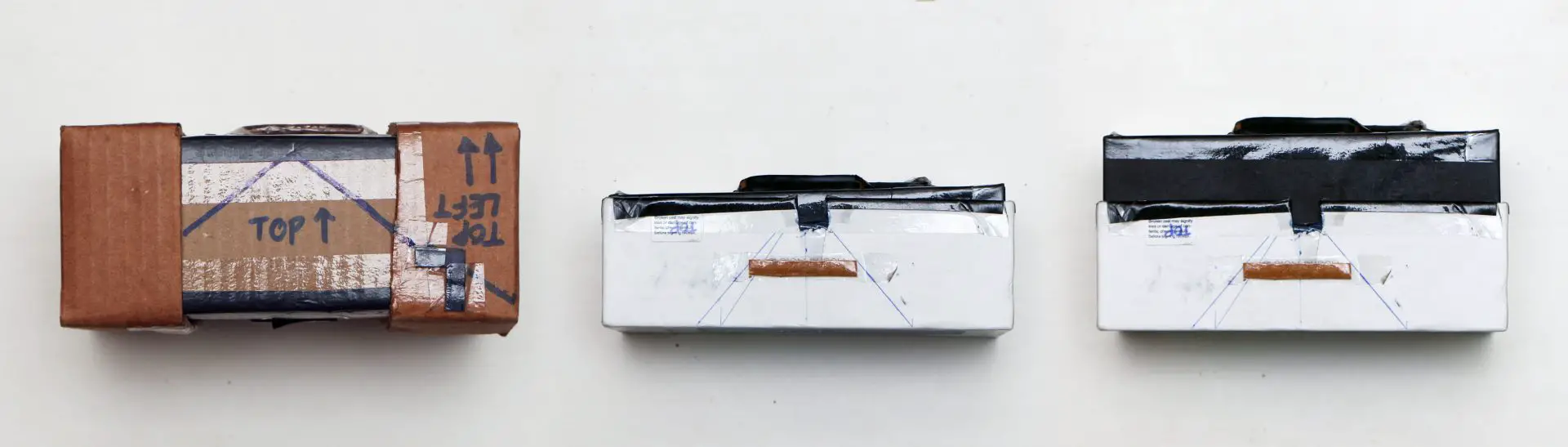
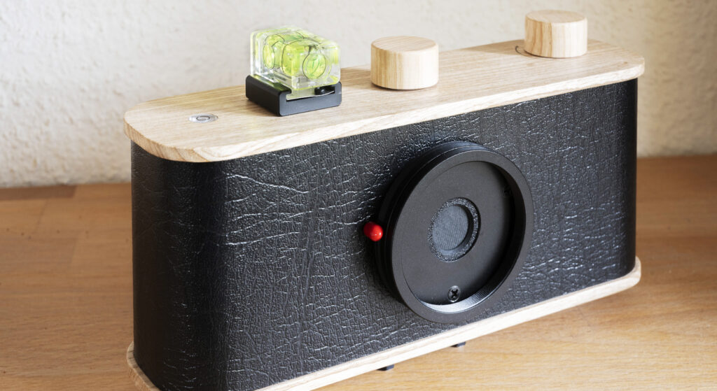
I used the two cameras, shown above, to take three photos. The first photo was taken with Nautilus, whose construction is described in an earlier post. For the test, I loaded it with 4×6″ (10×15cm) paper. Nautilus has a focal distance of 6cm.
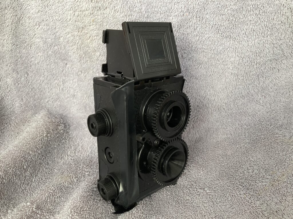
The second photo was taken on a camera called Burōni, named after the Japanese term for 120 film (in turn derived from the Kodak Brownie camera). I originally made it to take pictures on 120 film, but for the test I loaded it with 6×9cm paper – a smaller sensor than Nautilus. Burōni has a native focal distance of 5.5cm.
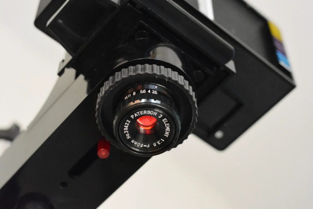
The fun thing about Burōni is that you can pull out the lid partway to increase the focal distance, just like a zoom lens (see photo below). So for the third photo – also taken on 6×9cm paper – I extended the focal distance to 8.5cm. Other things being equal, increasing the focal distance results in a smaller aperture (higher f-number), so the exposure time has to be increased accordingly.
The table below shows the sensor diagonal and focal distances for the three configurations described above, and the corresponding angle of view (35mm-equivalent focal length) as predicted by my calculator.
| Camera | Sensor diagonal | Focal distance | 35mm-eqvt focal length |
| Nautilus | 183mm | 6cm | 14mm |
| Burōni | 108mm | 5.5cm | 22mm |
| Burōni zoom | 108mm | 8.5cm | 34mm |
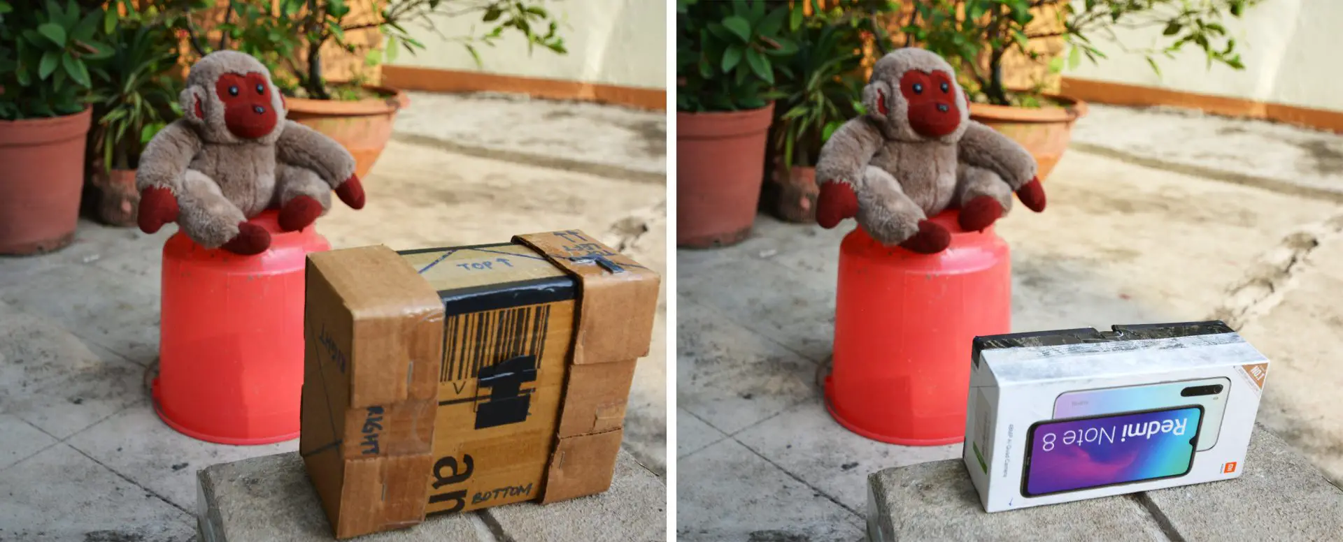
Now for the test results. In the image below, the left column has the three pinhole photos, all taken from the same camera-position but with different camera configurations. The right column has three photos taken with a digital camera placed in (roughly) the same position, using a zoom lens to approximate the pinhole focal lengths. I also annotated the images with the focal length – predicted 35mm-equivalent focal length for the pinhole photos, and actual focal length of the lens for the digital photos.
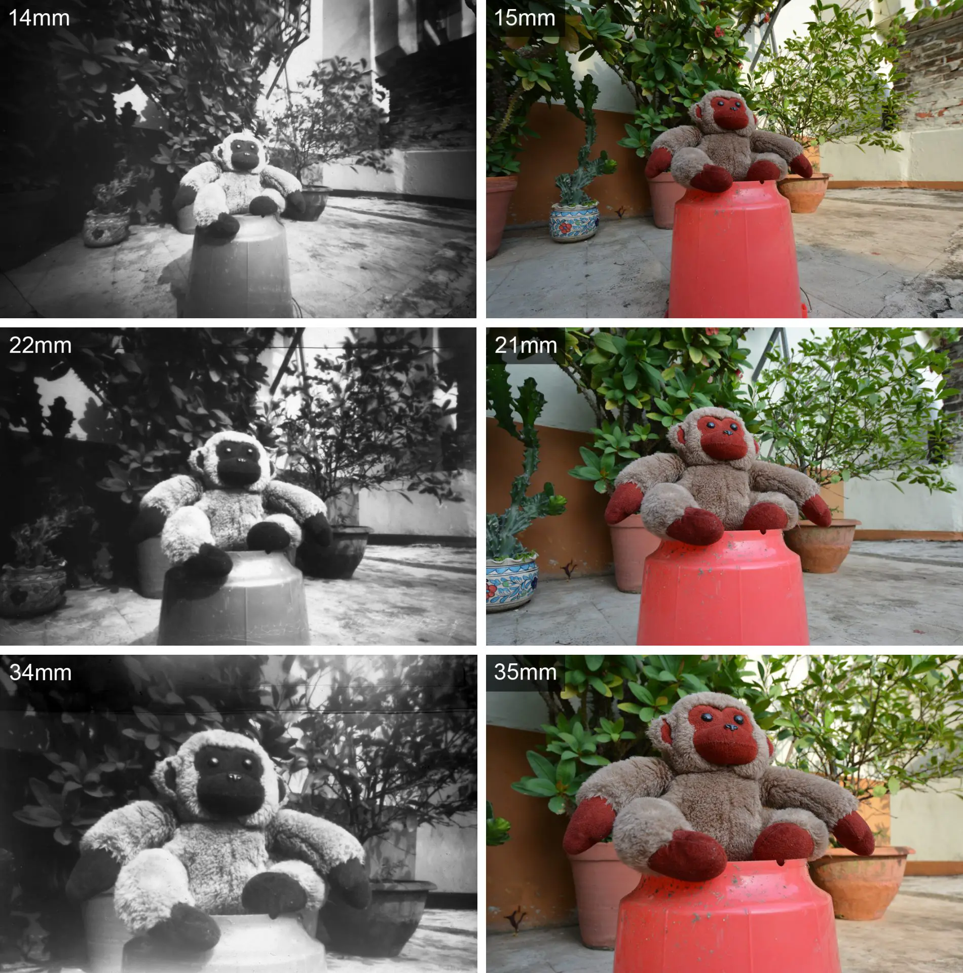
You can clearly see how, as the equivalent focal length increases (angle of view narrows), the camera “zooms in”. The angle of view for the pinhole and digital cameras also match quite well, if you make allowance for slight variations in camera placement. Which is to say, when I use a digital camera to replicate the focal length predicted by the calculator, I end up with similar images. The calculator works.
A couple of additional notes. The first pinhole photo is obviously an extreme wide-angle. The calculator predicts vignetting of 2.2 stops, at ¾ of the distance from centre to corner. And indeed you can see how the monkey is slightly overexposed, while the corners are kind of dark. The second photo is also wide-angle, but not quite as extreme. Vignetting is now down to a perfectly acceptable 0.3 stops (as before, at ¾ of the distance from centre to corner). Finally, in case you’re wondering, the lack of contrast in the third pinhole image is due to a slight light leak (it also has some marks on the top due to clumsy paper handling).
Conclusion
To sum up, a pinhole camera’s sensor size, focal distance and angle of view are interrelated. I made a calculator where you can enter any two of the variables (your choice), and it gives you the third. So you can, in theory, figure out what your parameters should be if, say, you want an angle of view similar to a 20mm or 50mm lens. And then you can build your pinhole camera accordingly, or – if you’ve built one already – you can predict what its angle of view will be.
As I said, mine is not the only calculator out there, but it’s the one which most closely matches my needs. Also, the formulae are all on the spreadsheet, so you can “look under the hood” if you like. Feel free to download a copy for your own use, and let me know if you think of any improvements.
There are other alternatives out there. MrPinhole seems to be the most popular. There is also the Pinhole Assist app which seems promising. Like my calculator (but unlike the other ones I’ve seen), it also gives you the 35mm-equivalent focal length. But Pinhole Assist is a paid app for iOS only, and as such I haven’t used it myself.
Needless to say, use whatever works for you – or if you prefer not to overthink it and just go with trial-and-error, that’s fine too! The most important thing is to have fun.
This post is part of my Pinhole Adventures series, documenting my pinhole photography journey and things I learn and do along the way. For more pinhole experiments as well as “lens photography”, feel free to check out my Instagram.
Share this post:


Comments
Rich on A Calculator for Pinhole Camera Design – by Sroyon
Comment posted: 10/08/2021
Now to go explore...
--Rich
Comment posted: 10/08/2021